
• Product Center

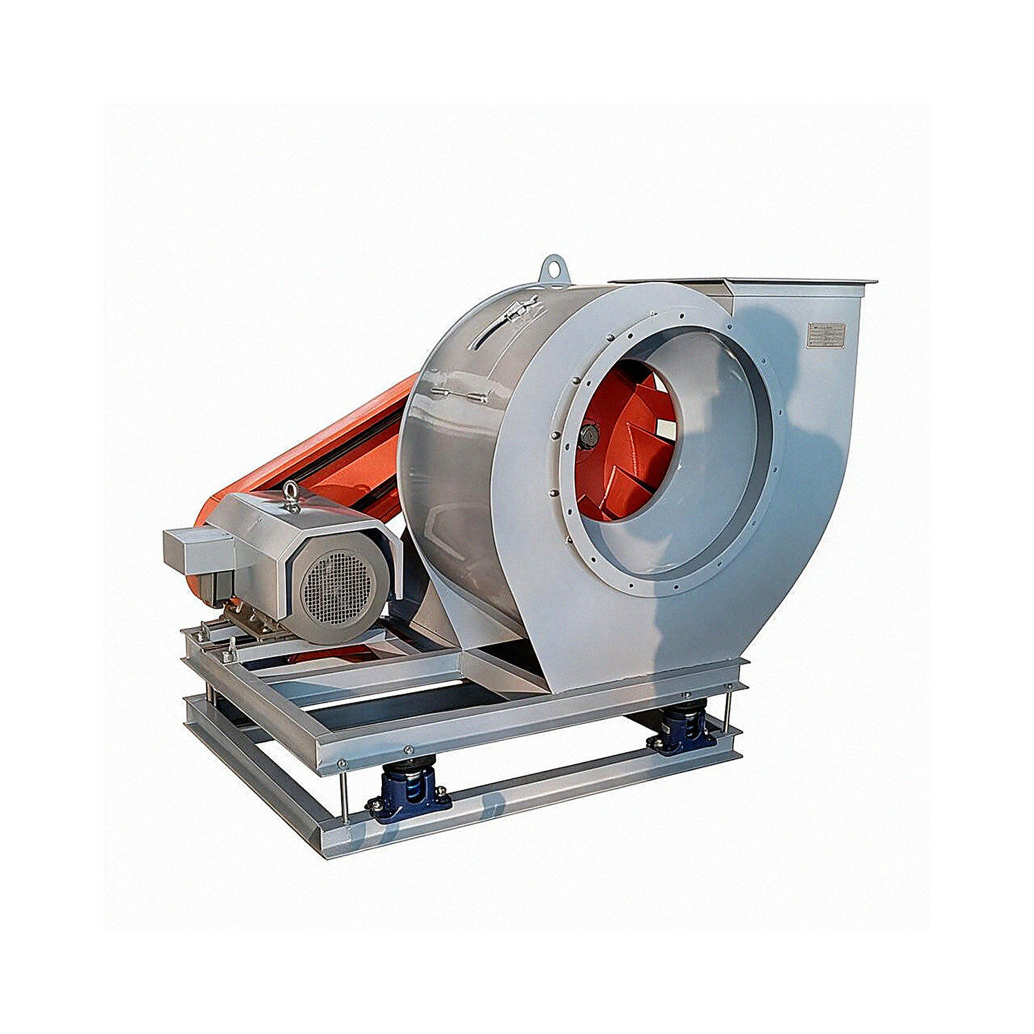
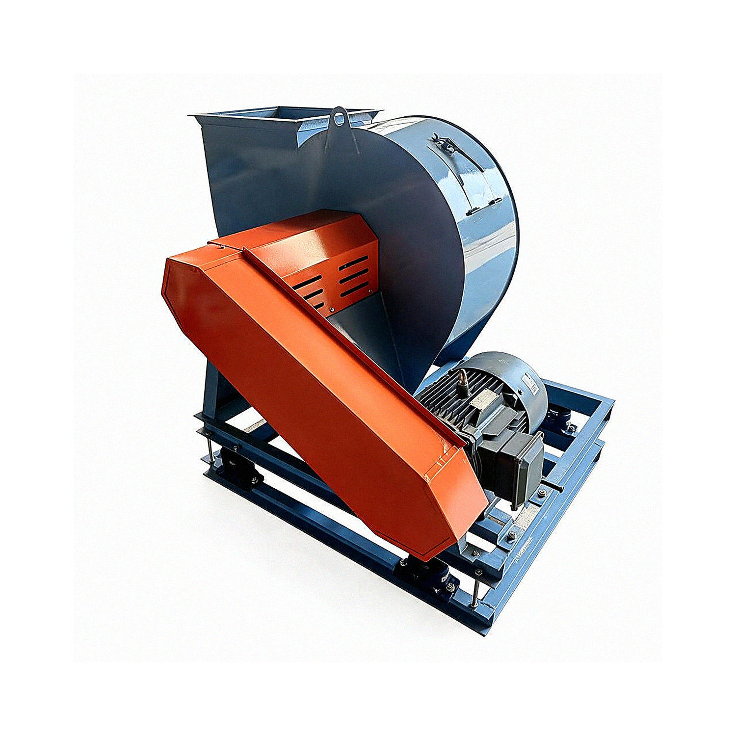
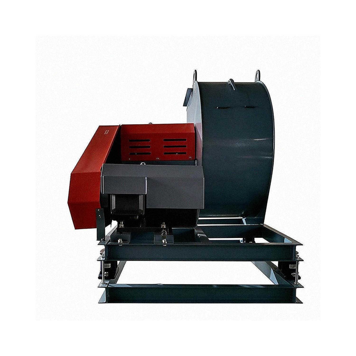
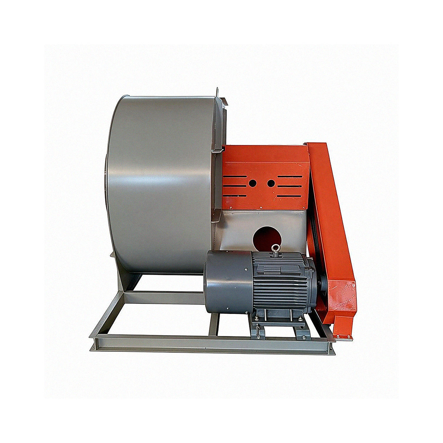
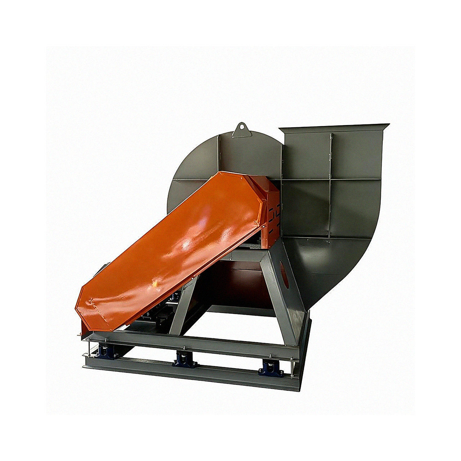
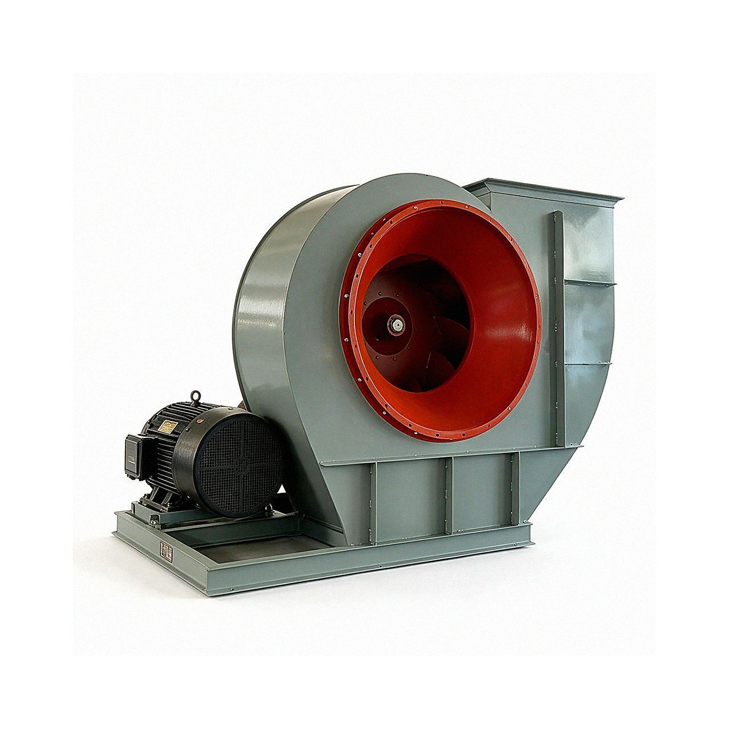
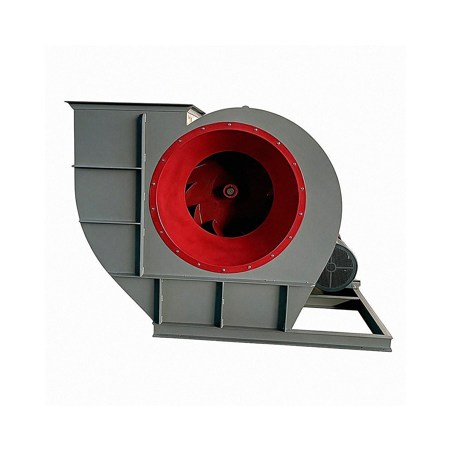
4-72C Centrifugal Fan

4-72 Centrifugal Fan

Applications

The 4-72 centrifugal fan is primarily used for indoor ventilation and air exchange in general large factories and large buildings, or for conveying air and other gases that are non-combustible, non-explosive, non-volatile, harmless to the human body, and non-corrosive to steel. The gases conveyed by the centrifugal fan must not contain viscous substances, and the dust and hard particles they contain must not exceed 150mg/m³,  and the gas temperature must not exceed 80℃.

The performance, selected components, and foundation dimensions of the B4-72 fan are the same as those of the 4-72 fan, and can be selected by referring to its catalog. The fan construction is basically the same as that of the 4-72 fan. Models No2.8~6A use B35-type motors with flanges and feet. For models No6~12C and D, select the YB-series motor corresponding to the Y-series motor in the selection table; the installation type is B.

The F4-72 centrifugal fan is made of stainless steel, fiberglass-reinforced plastic, or other corrosion-resistant materials. Its performance and foundation dimensions are the same as those of the 4-72 centrifugal fan.

The F-72 centrifugal fan was among the earliest fans used in China, and is also one of the most widely used. From high-rise buildings to underground railways, from boiler forced-draft applications to workshop ventilation,

from the northern frontier to the shores of the South China Sea, and from the western plateau to the eastern border, 4-72 fans can be found everywhere.


Configurations

Viewed from the motor end, a fan whose impeller rotates clockwise is called a “right-hand fan” and is denoted by “right”; a fan rotating in the opposite direction is called a “left-hand fan” and is denoted by “left”.

The fan outlet position is indicated by the outlet angle of the casing. Users must specify the required position when placing an order. For models No2.8~ND6, the outlet position can be adjusted from 0° to 225° in 45° increments. For models No8~12, the outlet position can be adjusted from 0° to 225° in 45° increments. For models NO16 and 20, the outlet angle is fixed at one of three positions—0°, 90°, or 180°—and cannot be adjusted; the required position must be specified when ordering.

The fan has four drive types: A, B, C, and D. For the 4-72 fan, models No2.8~5 use a Type A drive; No6 is available with either a Type A or Type C drive; No8~12 use either a Type C or Type D drive; and No16~20 use a Type B drive.

If the above model numbers, drive types, or outlet angles do not meet your production requirements, our factory can modify or design the fan to meet your needs.


Performance and Selection

This catalog provides only the dimensionless performance table and dimensionless performance curve for the No10 test fan. Dimensional performance parameters for other model numbers can be derived from these.

Figure 1: 4-72  No10       Dimensionless Performance Table for the Test Fan       The formulas for calculating dimensional parameters from dimensionless parameters are as follows:


image.png


Table 1: Dimensionless Performance Curve for the 4-72  No10     Test Fan


1

2

3

4

5

6

φ

0.1884

0.2051

0.2218

0.2361

0.25

0.2637

Medium

0.458

0.452

0.434

0.413

0.39

0.363

Wa

0.0335

0.0397

0.0465

0.0528

0.0594

0.0663

λ

0.0995

0.1045

0.1082

0.1106

0.1126

0.1137

nin

0.867

0.887

0.89

0.882

0.866

0.842


4-72   No2.8A, 3.2A, 3.6A                 Centrifugal Fan Performance and Component Selection Table


Fan model

Drive

type

Speed r/min


Serial No.

Flow rate m³/h

Total pressure

Pa

Internal efficiency %

Internal power

kw

Required power kw

Motor

Foundation bolts

GB799-76

(4 pcs)

Nuts

GB799-76

(4 pcs)

Washers

GB96-85

(4 pcs)

Model

Power kw


2.8


A


2900

1

1131

994

69.3

0.45

0.67


Y90S-2

(B35)


1.5


M8×220


M8


8

2

1310

966

73.2

0.48

0.72

3

1480

933

75.5

0.51

0.71

4

1659

887

76.8

0.53

0.74

5

1828

835

76.9

0.55

0.77

6

2007

770

75.6

0.57

0.79

7

2177

702

73.2

0.58

0.81

8

2356

606

69.3

0.57

0.80


3.2


A


2900

1

1688

1300

69.3

0.88

1.23


Y90L-2

(B35)


2.2


M8×220


M8


8

2

1955

1263

73.2

0.93

1.31

3

2209

1220

75.5

0.99

1.38

4

2476

1160

76.8

1.03

1.34

5

2729

1091

76.9

1.07

1.39

6

2996

1006

75.6

1.10

1.43

7

3250

918

73.2

1.13

1.47

8

3517

792

69.3

1.11

1.45


3.2


A


1450

1

844

324

69.3

0.11

0.16


Y90S-4

(B35)


1.1


M8×220


M8


8

2

978

315

73.2

0.12

0.17

3

1104

304

75.5

0.12

0.19

4

1238

289

76.8

0.13

0.19

5

1365

272

76.9

0.13

0.20

6

1498

251

75.6

0.14

0.21

7

1625

229

73.2

0.14

0.21

8

1758

198

69.3

0.14

0.21


3.6


A


2900

1

2664

1578

74.2

1.56

2.03


Y100L-2

(B35)


3


M10×220


M10


10

2

3045

1531

77.8

1.65

2.15

3

3405

1481

80.3

1.73

2.25

4

3786

1419

82.1

1.81

2.35

5

4146

343

82.6

1.86

2.42

6

4527

1256

81.8

1.92

2.50

7

4887

1144

79.5

1.95

2.53

8

5268

989

74.3

1.94

2.52


4-72 No3.6A, 4A, 4.5A Centrifugal Fan Performance and Component Selection Table


Fan model

Drive

type

Speed r/min


Serial No.

Flow rate m³/h

Total pressure

Pa

Internal efficiency %

Internal power

kw

Required power kw

Motor

Foundation bolts

GB799-76

(4 pcs)

Nuts

GB799-76

(4 pcs)

Washers

GB96-85

(4 pcs)

Model

Power kw


3.6


A


1450

1

1332

393

74.2

0.20

0.29


Y90S-4

(B35)


1.1


M8x220


M8


8

2

1522

381

77.8

0.21

0.31

3

1703

369

80.3

0.22

0.33

4

1893

353

82.1

0.23

0.34

5

2073

335

82.6

0.23

0.35

6

2263

313

81.8

0.24

0.36

7

2444

285

79.5

0.24

0.36

8

2634

247

74.3

0.24

0.36


4


A


2900

1

4012

2014

77

2.89

3.47


Y132S1-2

(B35)


5.5


M8x220


M8


8

2

4506

1969

80.3

3.05

3.66

3

4973

1915

82.5

3.18

3.82

4

5468

1830

84.1

3.28

3.94

5

5962

1723

84.6

3.35

4.02

6

6457

1606

83.7

3.42

4.11

7

6924

1459

81.4

3.43

4.11

8

7419

1320

77.5

3.49

4.19


4


A


1450

1

2006

501

77

0.36

0.54


Y90S-4

(B35)


1.1


M8x220


M8


8

2

2253

490

80.3

0.38

0.57

3

2487

476

82.5

0.40

0.60

4

2734

455

84.1

0.41

0.62

5

2981

429

84.6

0.42

0.63

6

3228

400

83.7

0.43

0.64

7

3462

363

81.4

0.43

0.64

8

3709

329

77.5

0.44

0.66


4.5


A


2900

1

5712

2554

77

5.21

6.00


Y132S-2

(B35)


7.5


M10×220


M10


10

2

6416

2497

80.3

5.49

6.32

3

7081

2428

82.5

5.74

6.60

4

7785

2320

84.1

5.92

6.81

5

8489

2184

84.6

6.04

6.95

6

9194

2036

83.7

6.17

7.09

7

9859

1849

81.4

6.17

7.10

8

10562

1673

775

630

724


4-72 No4.5A, 5A, 6A Centrifugal Fan Performance and Component Selection Table


Fan model

Drive

type

Speed r/min


Serial No.

Flow rate m³/h

Total pressure

Pa

Internal efficiency

%

Internal power kw

Required power kw

Motor

Foundation bolts

GB799-76

(4 pcs)

Nuts

GB799-76

(4 pcs)

Washers

GB96-85

(4 pcs)

Model

Power kw


4.5


A


1450

1

2856

634

77

0.65

0.91


Y90S-4

(B35)


1.1


M8x220


M8


8

2

3208

620

80.3

0.69

0.96

3

3540

603

82.5

0.72

1.00

4

3893

577

84.1

0.74

1.04

5

4245

543

84.6

0.76

1.06

6

4597

506

83.7

0.77

1.08

7

4929

460

81.4

0.77

1.08

8

5281

416

77.5

0.79

1.10


5


A


2900

1

7728

3187

77.6

8.72

10.02


Y160M2

-2

(B35)


15


M12×300


M12


12

2

8855

3145

81.8

9.35

10.76

3

9928

3074

84.7

9.90

11.39

4

11054

2962

86

10.47

12.04

5

12128

2792

86.1

10.82

12.44

6

13255

2567

84.6

11.07

12.72

7

14328

2335

82.1

11.22

12.90

8

15455

2019

77.6

11.09

12.75


5


A


1450

1

3864

790

77.6

1.09

1.42


Y100L1-4

(B35)


2.2


M10×220


M10


10

2

4427

780

81.8

1.17

1.52

3

4964

762

84.7

1.24

1.61

4

5527

735

86

1.31

1.70

5

6064

693

86.1

1.35

1.76

6

6628

637

84.6

1.38

1.80

7

7164

580

82.1

1.40

1.82

8

7728

502

77.6

1.39

1.80


6


A


1450

1

6677

1139

77.6

2.71

3.25


Y112M-4

(B35)


4


M10×220


M10


10

2

7650

124

81.8

2.91

3.49

3

8578

1099

84.7

3.08

3.70

4

9551

1059

86

3.26

3.91

5

10478

999

86.1

3.36

4.04

6

11452

919

84.6

3.44

4.13

7

12379836

82.1

3.49

4.19

8

13353

724

776

345

414


Fan Installation and Overall Dimensions

4-72-12, No2.8-6A Fan Installation and Overall Dimensions Table
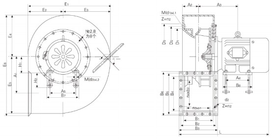

image.png


4-72-12, No2.8-6A Centrifugal Fan Installation and Overall Dimensions Table


Fan model

Inlet

Outlet


D₁


D₂


D₃

Connecting bolt specifications

M(d1) xL1

Bolt


B₁


B₂


B₃


B₄


B₅


B₆

Bolt holes

Quantity

Diameter

Quantity

Spacing

n1

d₂

nz

n₃xb₁

n₄xb₂

ND2.8


YB90S-2

Φ280

φ306

φ324

M6x10

8

196

228

251

224

256

278

Φ7

16

3x55

3x63

No3.2

YB90S-4

φ320


Φ350


Φ367


M6X10

16

224

256

279

256

288

310


Φ7

16

3x60

3x72

YB90L-2

No3.6

Applicable motor (B

YB90S-4

φ360


Φ394

φ416


M6X16

16

252

284

308

288

320

343

φ7

16

3x70

3x80

¥. 100L-2


ND4

YB90S-4

φ400


Φ440


Φ462


M6X16

16

280

315

336

320

355

374

φ7

20

4×60

4×70

YB 132S1-2 Y

NQ4.5

Type 35(

YB90S-4


Φ450


Φ490

φ512


M8X20

16

315

360

371

371

395

415

φ7

20

4x70

4x78

YB132S2-2


N05


YB100L1-4

φ500

φ550

φ572


M8X20

16

350

385

406

406

435

456


Φ7

20

4x75

4×88

YB Y

160M2-2


No6

YB Y

100L-6

φ600

①650


Φ676


M8X20

16

420

455

476

476

511

536

φ7

24

5x75

5x87

YB Y

112M-4


4-72 Centrifugal Fan Performance Selection Chart
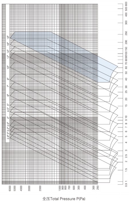

image.png


4-72-3 Type A Centrifugal Fan Performance Selection Chart


image.png


Freq.

Hz

63

125

250

500

100

2000

4000

8000

Lwrel

dB

-14.5

-13

+3.5

-9

-9.5

-14

-19

-24.5


4-72-2.8 Type A Centrifugal Fan Performance Selection Chart


image.png


Freq.

Hz

63

125

250

500

100

2000

4000

8000

Lwrel

dB

-14.5

-13

+3.5

-9

-9.5

-14

-19

-24.5


4-72-3.5 Type A Centrifugal Fan Performance Selection Chart
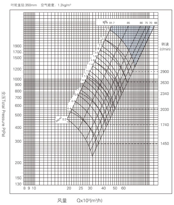

image.png


Freq.

Hz

63

125

250

500

100

2000

4000

8000

Lwrel

dB

-14.5

-13

+3.5

-9

-9.5

-14

-19

-24.5


4-72-3.2 Type A Centrifugal Fan Performance Selection Chart
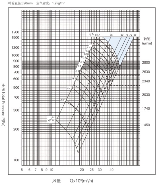

image.png


Freq.   Hz

63

125

250

500

100

2000

4000

8000

Lwrel   dB

-14.5

-13

+3.5

-9

-9.5

-14

-19

-24.5


4-72-4 Type A Centrifugal Fan Performance Selection Chart
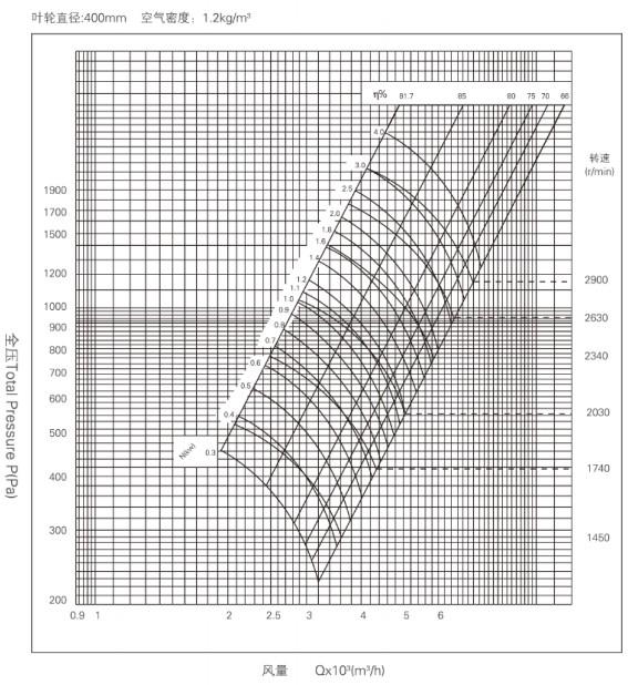

image.png


Freq.

Hz

63

125

250

500

100

2000

4000

8000

Lwrel

dB

-14.5

-13

+3.5

-9

-9.5

-14

-19

-24.5


4-72-4.5 Type A Centrifugal Fan Performance Selection Chart
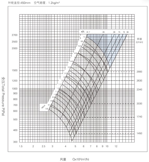

image.png


Freq.

Hz

63

125

250

500

100

2000

4000

8000

Lwrel

dB

-14.5

-13

+3.5

-9

-9.5

-14

-19

-24.5


4-72-5 Type A Centrifugal Fan Performance Selection Chart
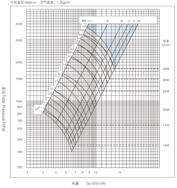

image.png


Freq.

Hz

63

125

250

500

100

2000

4000

8000

Lwrel

dB

-14.5

-13

+3.5

-9

-9.5

-14

-19

-24.5


4-72-6 Type A Centrifugal Fan Performance Selection Chart
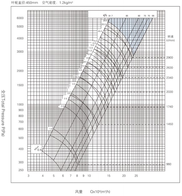

image.png


Freq.

Hz

63

125

250

500

100

2000

4000

8000

Lwrel

dB

-14.5

-13

+3.5

-9

-9.5

-14

-19

-24.5


Frequently Asked Questions

A:

Yes. Selection should be based on the actual airflow, system resistance, conveyed medium, and installation conditions. Final performance is subject to the model data confirmed by Haitong and the technical documents for the order.

A:

Haitong’s existing product information confirms that they are suitable for general ventilation and air conveyance, including ventilation in industrial plants, general exhaust, air supply for equipment, duct ventilation, and exhaust applications used with dust collection systems.

A:

This can be evaluated based on the project's power supply conditions. However, a change in frequency affects the motor speed, airflow, pressure, and power, so the selection must be reviewed again for the required frequency.

A:

They can be confirmed based on the selected model and project interfaces. Hightong’s existing product documentation confirms a circular inlet and rectangular outlet configuration. The final connection dimensions should be finalized using drawings or technical confirmation documents before production.

A:

Haitong’s existing 4-72 product documentation lists the air outlet direction as customizable. The specific rotation direction and outlet angle should be confirmed based on the site layout, duct connections, and final model.

A:

Can the 4-72 centrifugal fan be used in dust collection systems?

A:

This should not be stated as a general claim. Fire smoke exhaust applications require specific temperature-resistance requirements, appropriate fan selection, and the inspection or certification documents required for the project. A standard 4-72 product page should not make claims about fire smoke exhaust performance.

A:

We can assess the airflow, pressure, air outlet direction, motor configuration, interface dimensions, base, and related accessories based on project drawings. The final manufacturing scope is subject to the drawings and order technical documents confirmed by both parties.

4-72C Centrifugal Fan

Please provide the model, airflow, total/static pressure, installation orientation, air inlet and outlet configuration, material, insulation, motor voltage/frequency, control method, filter module, smoke control and fire protection requirements, quantity, and packaging requirements. Performance, dimensions, and certification information are subject to the confirmed product and order documents.


haitong@haitonghvac.com