


Applications:
Wide airflow adjustment range and other advantages.
This fan can be driven by a two-speed motor with direct drive. Its compact structure allows automatic control. To accommodate seasonal changes, the operating condition can be adjusted using a two-speed motor; to accommodate day-to-night temperature changes, the operating condition can be changed using adjustable stationary blades, achieving power savings and energy efficiency. Taking the FZ35-NO.20 fan as an example, at a speed of 970r/min in summer, the required power is 40kw; at 730r/min in winter, only 17.5kw is required.
Types:
FZ40-11 fans are available in sizes NO.8, 9, 10, 11, 12, 14 and 16. FZ35-11 fans are available in sizes 18, 20 and 22.4, making 10 sizes in total.
There are three blade-count options for different fan sizes: 5, 8 or 10 blades.
The blades can be installed at one of five angles: 8°, 11°, 14°, 17° or 20°.
For each fan size, air pressure, airflow and power consumption vary according to the number of blades, blade installation angle, rotational speed and stationary guide vane angle.
Structural features:
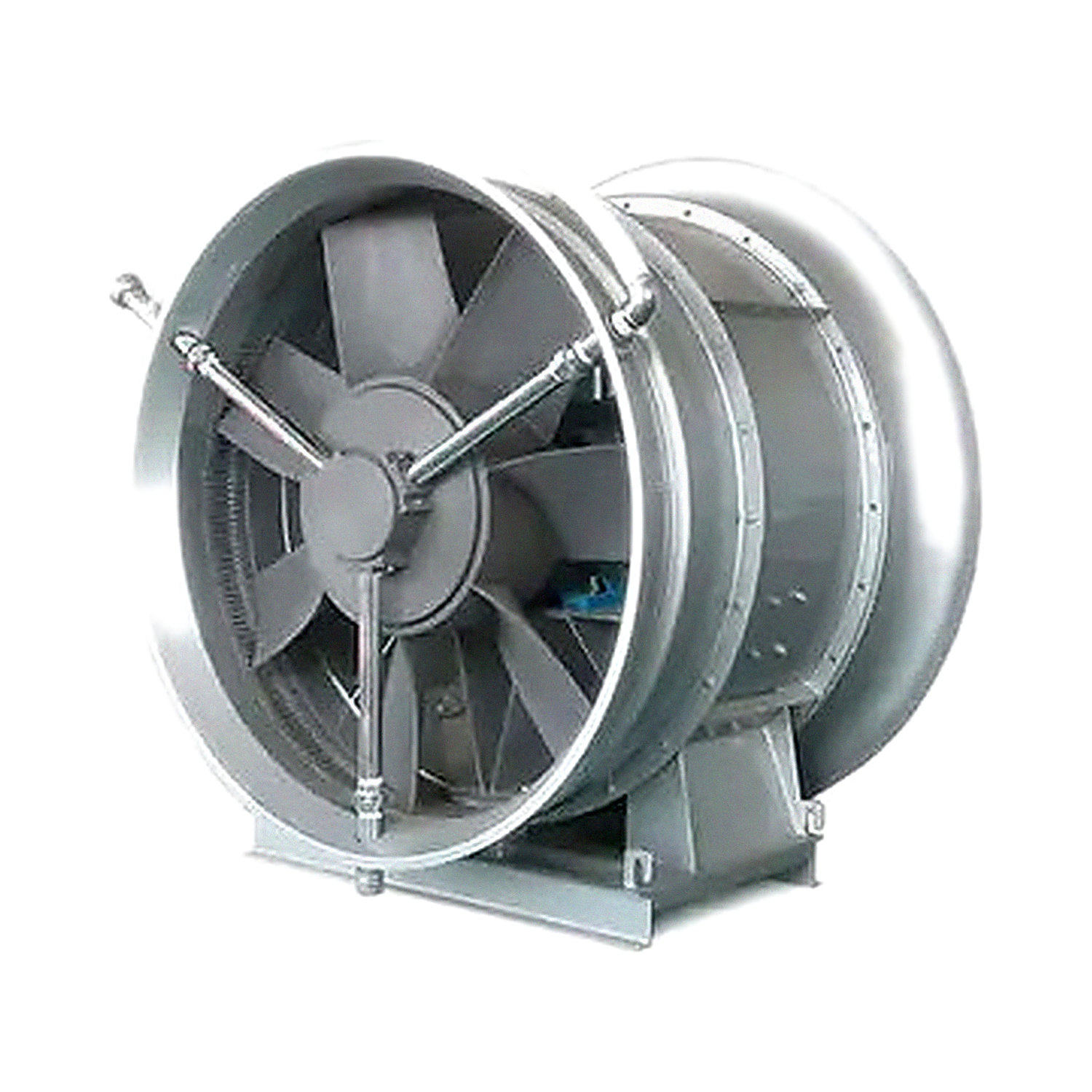
This fan mainly consists of an impeller, casing, inlet collector, damper (adjustable stationary-blade mechanism) and diffuser. The FZ40-11 NO.8–11.2 fans are not supplied with a damper or diffuser.
The impeller consists of blades, a hub, a shaft sleeve, two-piece clamping blocks, a cover plate and a shroud. The blades are twisted airfoil blades, and both the blades and hub are made of high-strength ZL104 cast aluminum. The blades are secured to the cover plate by two-piece clamping blocks. Loosening the two screws on the clamping blocks allows the blade angle to be adjusted as required. The shaft sleeve also has grooves and screw holes to facilitate installation and removal of the impeller. The shroud is made of LF21 and secured to the clamping blocks with screws. To prevent corrosion of the components, the surfaces of the connecting parts are galvanized. The impeller is directly coupled to the motor. Motors of different specifications are selected for different operating conditions; the motors are treated for moisture, mold and salt-spray resistance (“TH”). Fan performance is shown in the performance table.
The inlet collector, casing and diffuser are made of thin steel plate and structural sections.
The damper consists of 23 blades, a pneumatic-cylinder connecting rod and an annular body. It is installed axially at the front of the main fan duct, and its adjustment range is from 0° (fully open) to 40°. Its
adjustment principle is as follows: compressed air drives the pneumatic cylinder. As the pressure changes, the damper blades change angle to regulate pressure and airflow. To meet different user requirements, the damper (stationary guide vanes) can also be adjusted by motor or manually; please specify the required option when ordering.
This series of fans can be installed vertically or horizontally. Horizontal installation can be configured, according to user requirements, for wall mounting (without the support section) or floor mounting (without duct section II). Please specify the installation type when ordering. Also specify whether the fan will operate in forced-draft or induced-draft mode so that the manufacturer can assemble and supply it accordingly.
To better suit operating conditions, the outlet dynamic pressure pd for this fan series is calculated using a C3 value. If the previous method using a C2 value is applied, the resulting total pressure efficiency will be higher than the values listed in the table.
Frequently Asked Questions
Please provide the model, airflow, total/static pressure, installation orientation, air inlet and outlet configuration, material, insulation, motor voltage/frequency, control method, filter module, smoke control and fire protection requirements, quantity, and packaging requirements. Performance, dimensions, and certification information are subject to the confirmed product and order documents.