


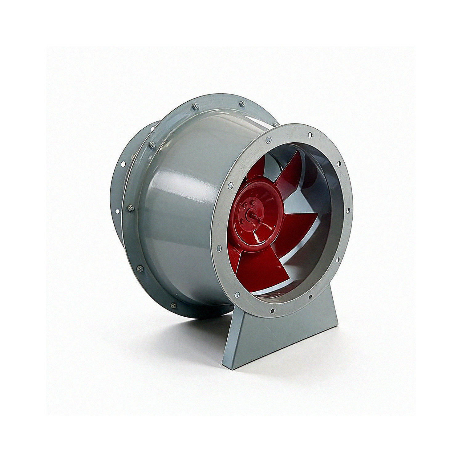
SJG Series Mixed-Flow Inline Fans
Applications
The specific speed of SJG series mixed-flow fans falls between that of centrifugal and axial fans. They combine the high pressure coefficient of centrifugal fans with the high flow coefficient of axial fans, while also offering a wide high-efficiency operating range.
In addition to these distinctive aerodynamic characteristics, the structural design of mixed-flow inline fans greatly simplifies engineering design and installation. The air inlet and outlet are on the same axis and have the same dimensions. Flanges allow connection to ducts of the same diameter, making installation very convenient. Unlike centrifugal fans, which require a 90° bend in the duct during installation, mixed-flow inline fans take up less space and do not affect duct layout or routing. They are ideal for pressurizing straight ducts and for supply and exhaust ventilation. Their compact design is especially advantageous in plant rooms with limited space.
SJG series high-efficiency, low-noise mixed-flow inline fans are widely used in ventilation and air-conditioning systems in civil buildings, as well as in various industrial production sectors.
They can replace low-pressure centrifugal fans, reducing investment and floor space while simplifying design and installation. Mixed-flow inline fans are the best choice for duct ventilation applications where axial fans cannot provide sufficient pressure.
SJG mixed-flow FRP inline fans can convey air and corrosive gases. With an explosion-proof motor, they can also convey flammable and explosive gases. The conveyed gas temperature can reach 80℃.
Structural Features
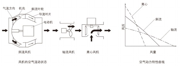
Compared with centrifugal and axial fans, mixed-flow inline fans have a distinctive linear configuration and aerodynamic parameters that fall between those of the two fan types. A comparison of their basic structures and airflow patterns is shown in the figure below; a comparison of their aerodynamic performance curves is shown in the chart.
SJG Mixed-Flow Fan Technical Performance Parameters
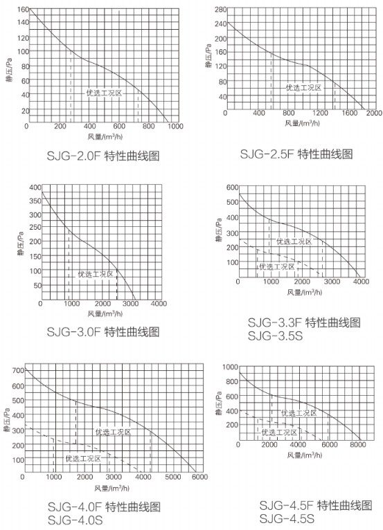
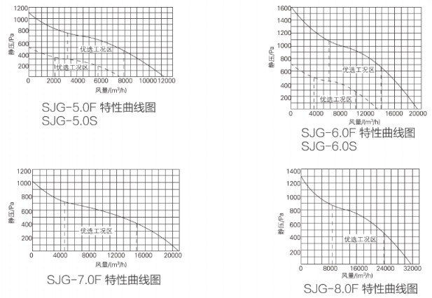
Performance and Selection
Dimensions and Installation Dimensions
SJG Series Mixed-Flow Inline Fan Dimensions and Installation Drawing
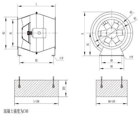
SJG Series Mixed-Flow Inline Fan Dimensions and Installation Table
Note: To ensure proper installation dimensions for users, the base mounting holes (4-center) are for reference only. Unless otherwise specified by the user, fan flanges are generally not drilled. Special requirements can be accommodated upon request.
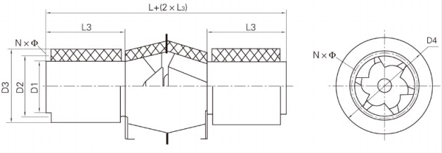
SJG Series Mixed-Flow Inline Fan Dimensions and Installation Table
Note: The silencer is supplied separately and must be specified when ordering.
Frequently Asked Questions
Please provide the model, airflow, total/static pressure, installation orientation, air inlet and outlet configuration, material, insulation, motor voltage/frequency, control method, filter module, smoke control and fire protection requirements, quantity, and packaging requirements. Performance, dimensions, and certification information are subject to the confirmed product and order documents.