


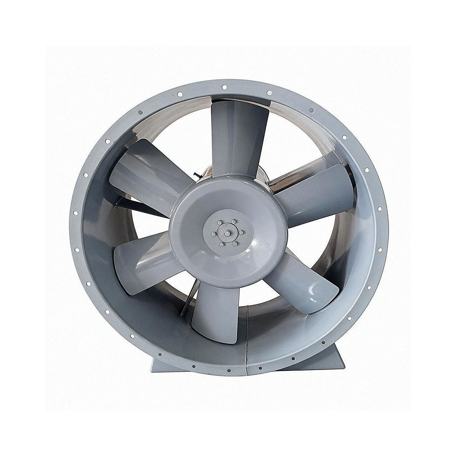
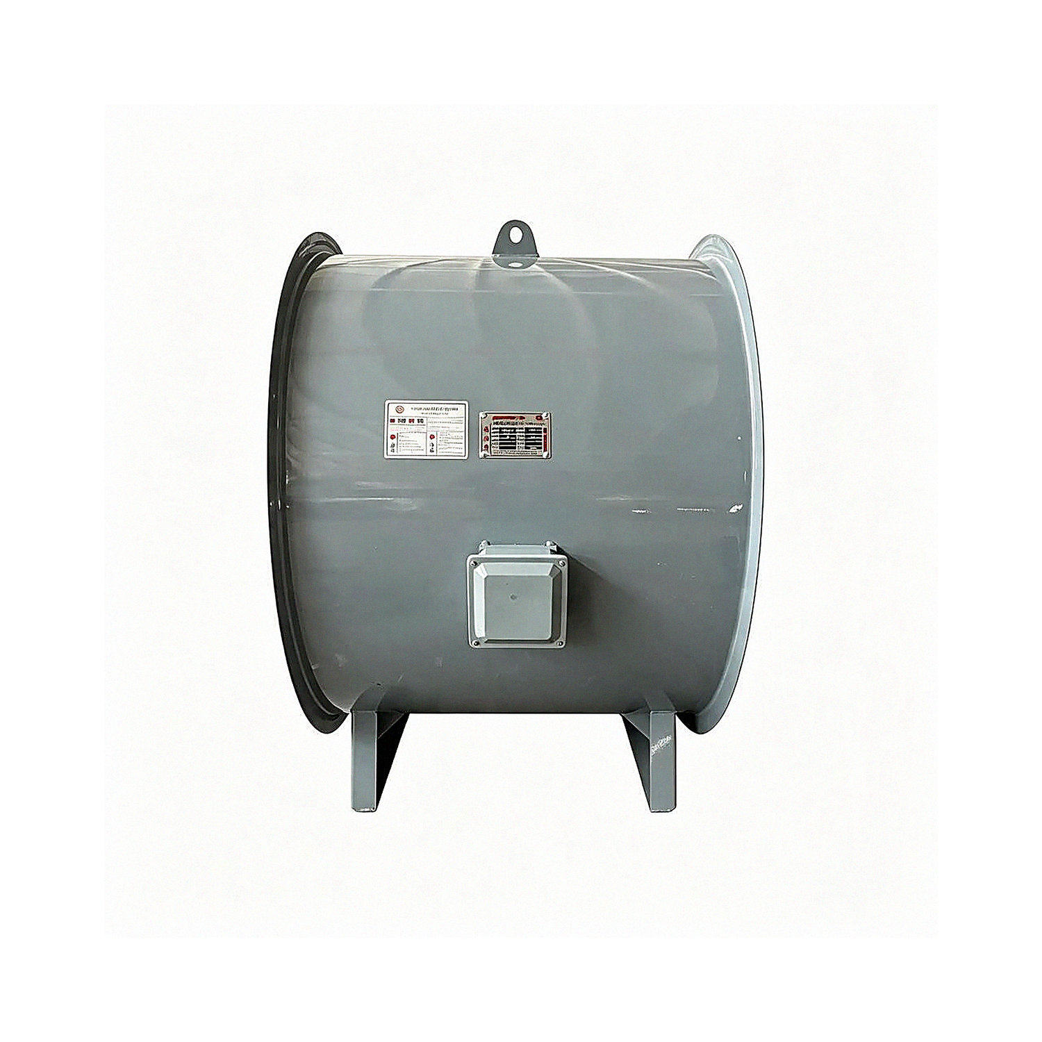
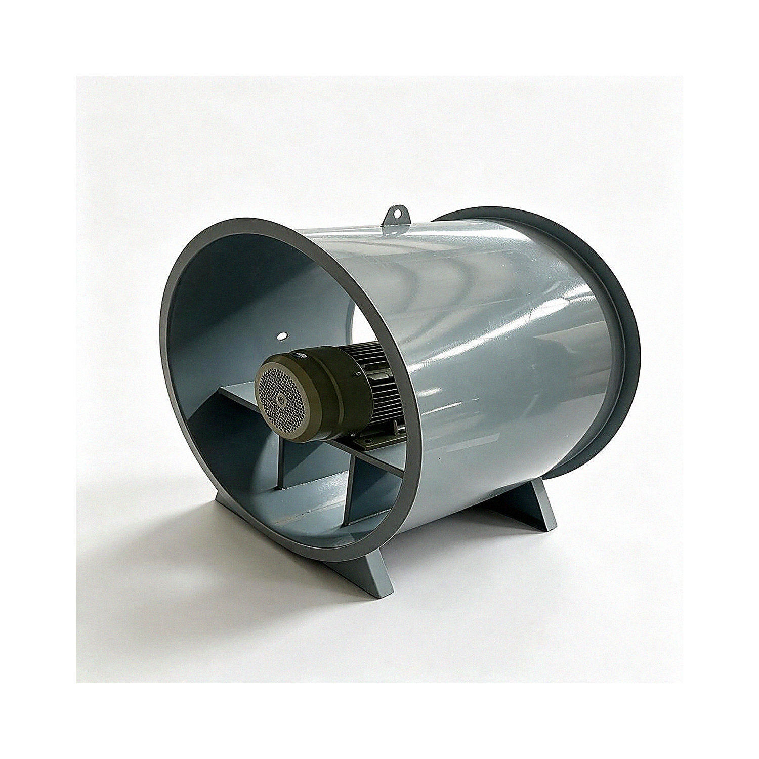
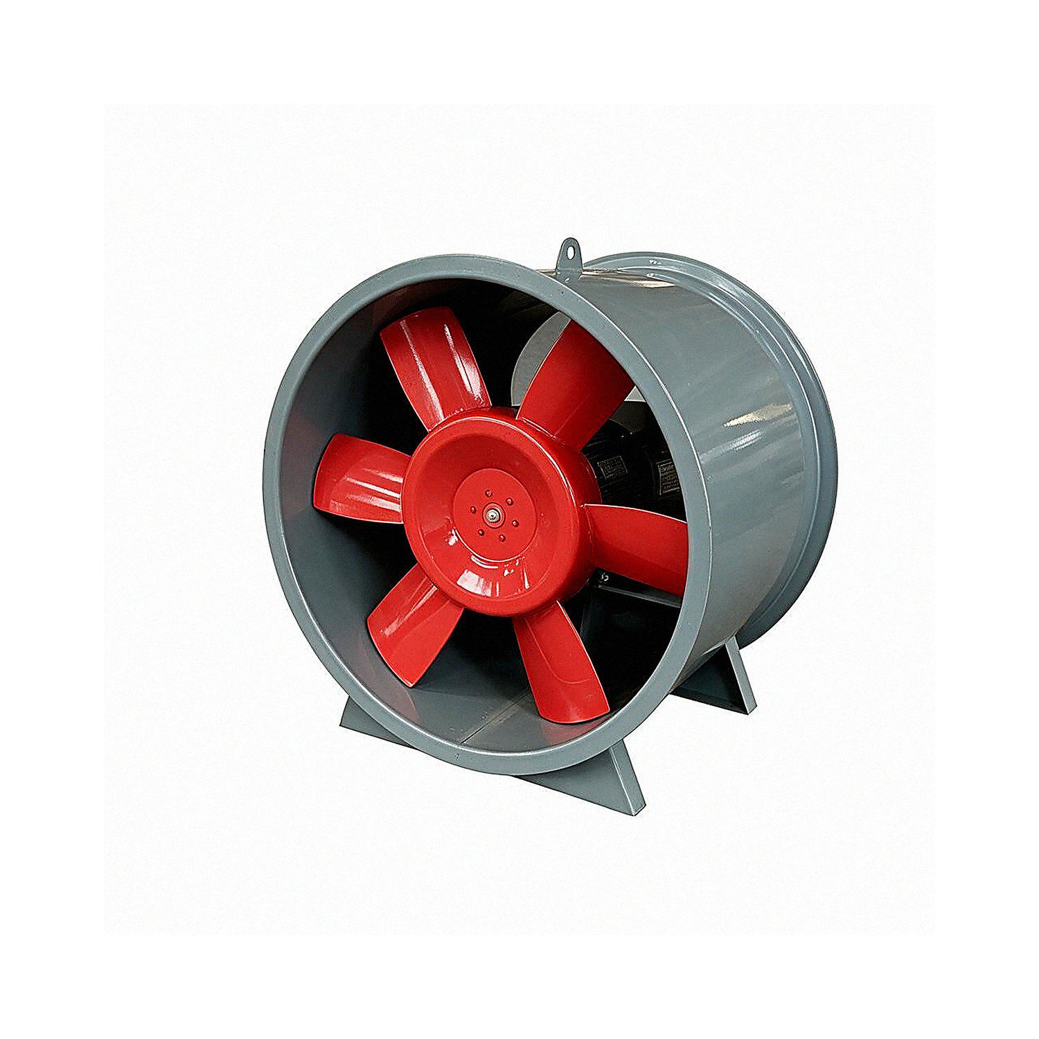
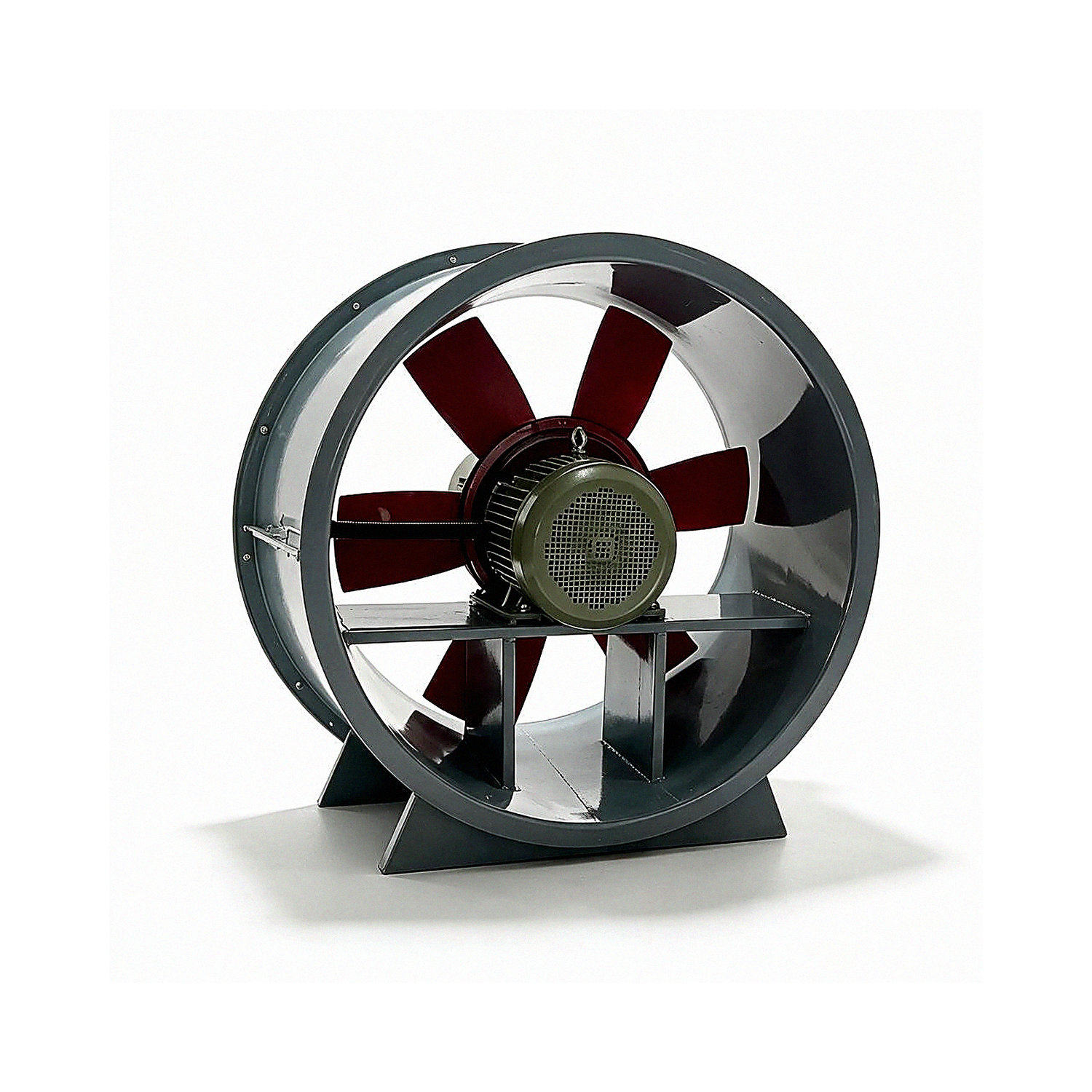
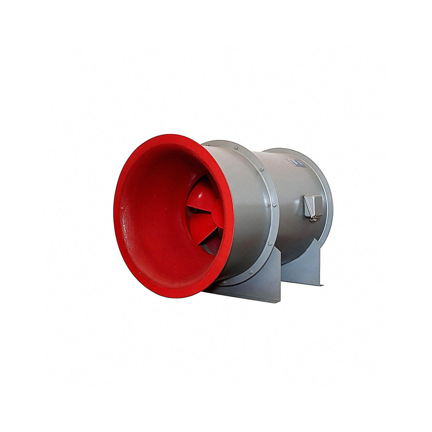
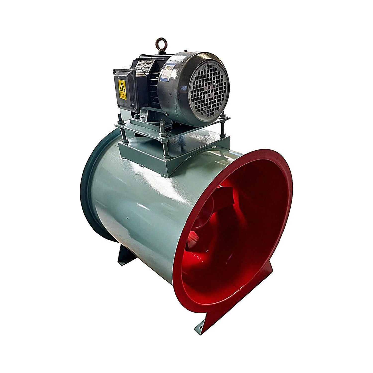
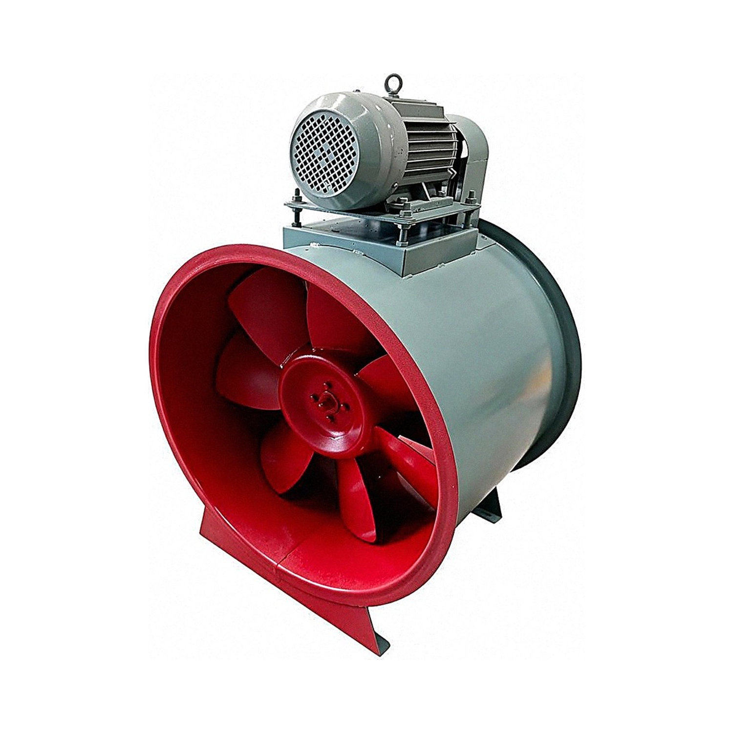
SWF Series Mixed-Flow Fans
1. High efficiency and a wide high-efficiency range
This fan is a high-tech product designed and developed using advanced CAD software, multi-objective optimization, and performance prediction. It uses the oblique-flow meridional acceleration method (also known as the mixed-flow fan design). Compared with an axial-flow fan of the same size, it delivers higher pressure; compared with a centrifugal fan of the same size, it delivers greater airflow. It features high efficiency and a wide high-efficiency range.
2. Compact structure, easy installation, and reliable operation:
At the same airflow and pressure, this fan is smaller than an axial-flow or centrifugal fan. It can be connected directly to ductwork and installed horizontally or vertically, making it easy to operate and use while ensuring reliable operation.
3. Low noise:
The fan casing is specially designed to significantly reduce vortex noise. Under operating conditions with the same airflow and pressure per unit, the A-weighted sound level can be reduced by 2–3 dB(A). It can also achieve relatively high fan pressure at a lower speed. In supply and exhaust ventilation systems for industrial and mining enterprises and high-grade civil buildings, it can replace low-pressure centrifugal fans or high-pressure axial-flow fans without requiring extensive noise-control measures.
4. Wide range of applications:
This series is available in single-speed and two-speed models. The fan installation angle, number of blades, and rotational speed can be adjusted to meet the requirements of different applications.
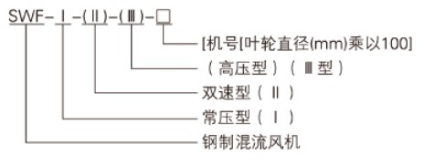
Designation Code Explanation
SWF Series Mixed-Flow Fan: Operation, Maintenance, and Care
1. Maintenance
a. Before installation, carefully check the impeller and casing for damage or deformation caused during transportation. If any is found, repair the parts before installation;
b. Check whether the blades are rubbing against the casing due to loose connecting screws. If the clearance between the blades and casing is uneven, adjust it before installation;
c. Before starting the fan, first check the fan and ductwork for any objects that could obstruct rotation;
d. Check that the motor insulation is in good condition. After connecting the power supply, check for friction, impact, or abnormal vibration;
e. During normal operation, shut down the fan immediately for inspection if any of the following occurs: ① the motor temperature rise exceeds 70℃; ② white smoke comes from the motor; ③ severe vibration or loud rubbing sounds occur.
2. Analysis of common fan faults:
Fan vibration can have many causes. Check the following:
a. The impeller rubs against the casing, producing abnormal noise and vibration;
b. The support base bolts are not tightened, which can also cause significant vibration;
c. The impeller has deformed under pressure during transportation, or vibration is caused by loose bolts;
d. The screws connecting the impeller to the shaft sleeve are loose, or the main shaft is bent or deformed;
e. Loose screws connecting the support to the motor can cause impeller imbalance; damaged bearings can also cause severe vibration.
3. Overheating
If the motor temperature rises excessively after operating for a period of time at normal ambient temperature, this may be caused by:
a. Damaged motor bearings or insufficient clearance that does not meet requirements;
b. Misalignment between the shaft and bearings, or misalignment between the two bearings;
c. Excessive resistance causing the motor to operate under overload;
d. Low power supply voltage or phase loss in a three-phase motor.
Fan Performance Parameter Tables
SWF-1 Model
SWF-1I Model
SWF- I Model
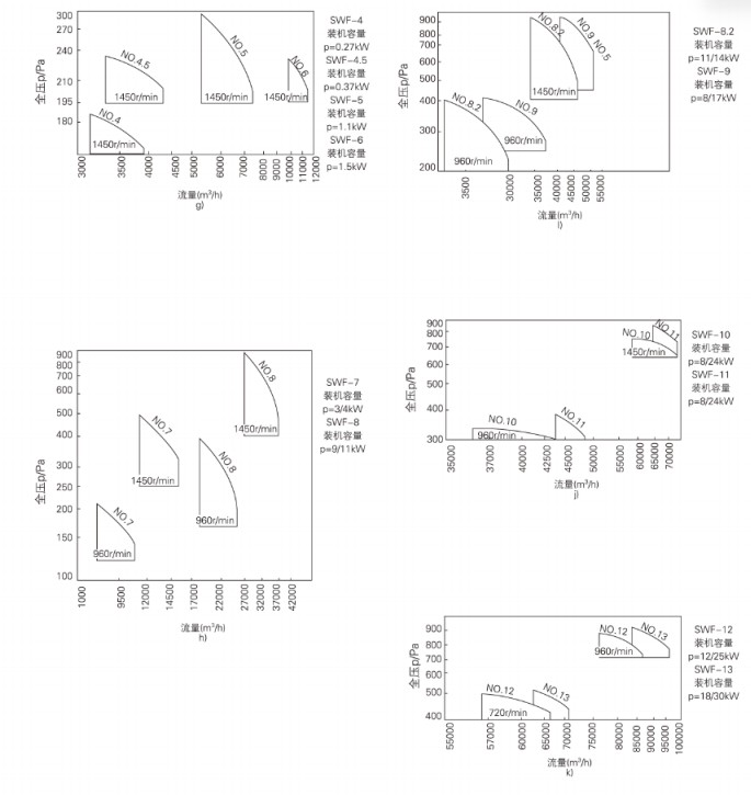
Performance Curves for SWF Series Mixed-Flow Fans

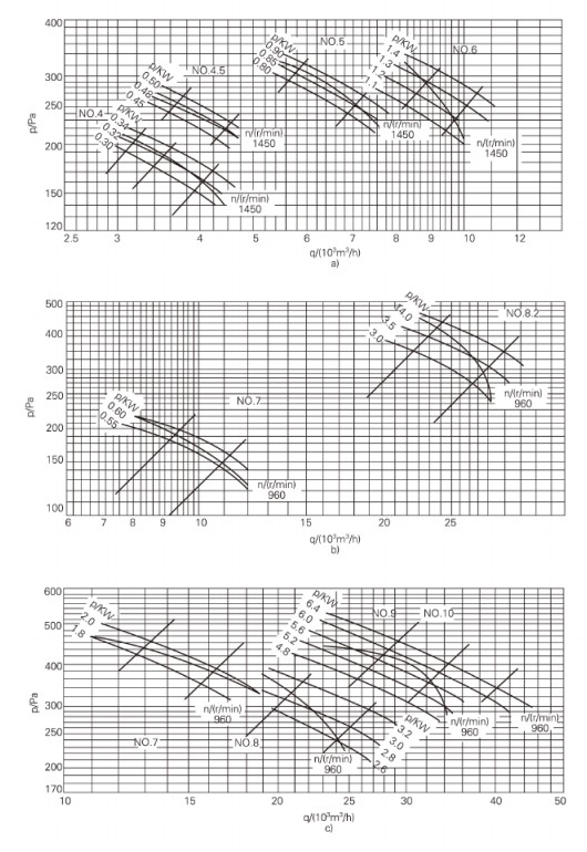
Dimensions and Installation Dimensions of SWF Series Mixed-Flow Fans
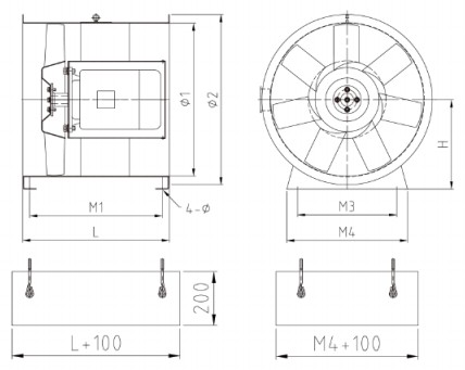
Dimensions and Installation Dimensions of SWF-I Mixed-Flow Fans
Dimensions and Installation Dimensions of SWF-II Mixed-Flow Fans
Dimensions and Installation Dimensions of SWF-IⅢ Mixed-Flow Fans
Note: 1. To ensure that the installation dimensions meet the user's requirements, the base mounting holes (4-φ) are for reference only. Unless otherwise specified by the user, fan flanges are generally not drilled. Special requirements can be accommodated upon request.
2. Products below size 7# generally use a casing without an inner cylinder. Special requirements can be accommodated upon request.
Illustrations of Installation Methods (Airflow Direction) for SWF Series Mixed-Flow Fans
1. Illustrations of installation methods (airflow direction)
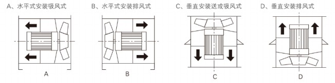
2. Installation instructions
A. The fan can be ducted for supply or exhaust operation as shown above. For applications with higher noise requirements, install flexible canvas connectors at the air inlets and outlets.
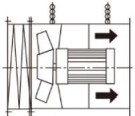
B. The fan can be suspended, mounted on supports, or installed using concrete inserts in a wall. It can also be manufactured according to user requirements.

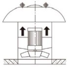
C. For vertical installation in supply or exhaust mode on a roof, a weather hood can be added to create a roof-mounted ventilation fan.
Frequently Asked Questions
Yes. Selection should be based on the project’s airflow requirements, system resistance, installation space, and the specifications of the selected fan. Final performance is subject to the model data confirmed by Haitong.
The choice should be based on a comprehensive assessment of airflow, system resistance, installation space, and noise requirements. Haitong’s current materials position mixed-flow fans for duct ventilation applications that require a balance of airflow and pressure, while axial-flow fans are presented as a distinct product category for general ventilation, exhaust, and air conveyance. The final selection should be based on the actual operating point.
We can assess this based on the project's power supply conditions. However, 50 Hz and 60 Hz affect motor speed, airflow, pressure, and power, so the selection must be reviewed again for the required frequency.
A mixed flow fan can be used in a duct ventilation system. Please provide the duct dimensions, connection method, and system resistance so we can confirm the connection dimensions, installation direction, and fan performance.
This can be confirmed based on the selected model and site layout. Before production, the installation direction, connection locations, and maintenance clearance should be verified through technical confirmation or the GA drawing.
They can be evaluated based on Haitong’s current product structure and project requirements. The motor arrangement, connection method, and maintenance requirements should be confirmed together with the final model.
This should not be assumed. Fire smoke exhaust applications require the selection of a dedicated high-temperature smoke exhaust fan, appropriate temperature resistance, and the test or certification documentation required for the project. A standard mixed-flow fan product page should not directly claim fire smoke exhaust performance.
The appropriate construction, materials, motor, and surface treatment can be evaluated based on the medium temperature, dust conditions, corrosiveness, and project specifications. However, standard mixed-flow fans should not be universally described as high-temperature, explosion-proof, or corrosion-resistant products.
Please provide the model, airflow, total/static pressure, installation orientation, air inlet and outlet configuration, material, insulation, motor voltage/frequency, control method, filter module, smoke control and fire protection requirements, quantity, and packaging requirements. Performance, dimensions, and certification information are subject to the confirmed product and order documents.