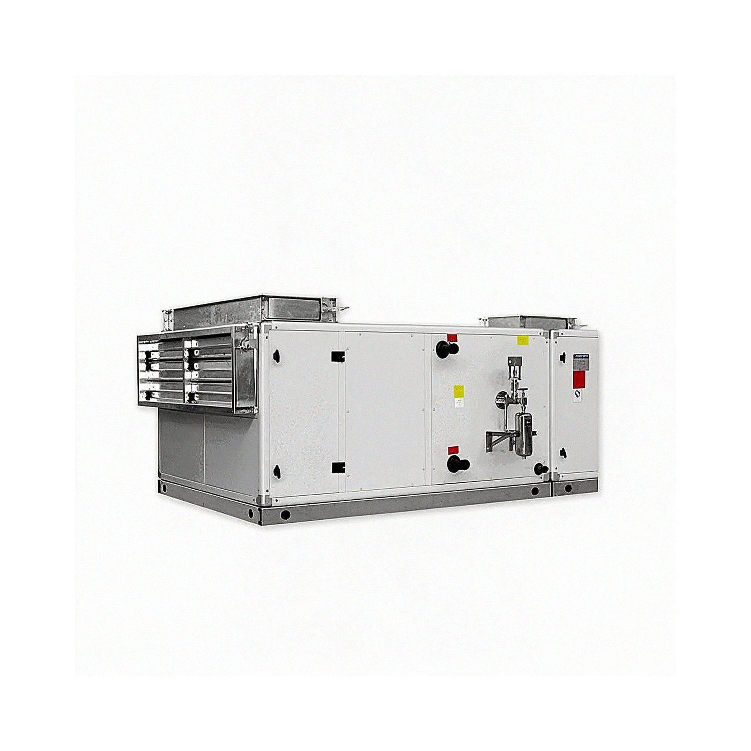
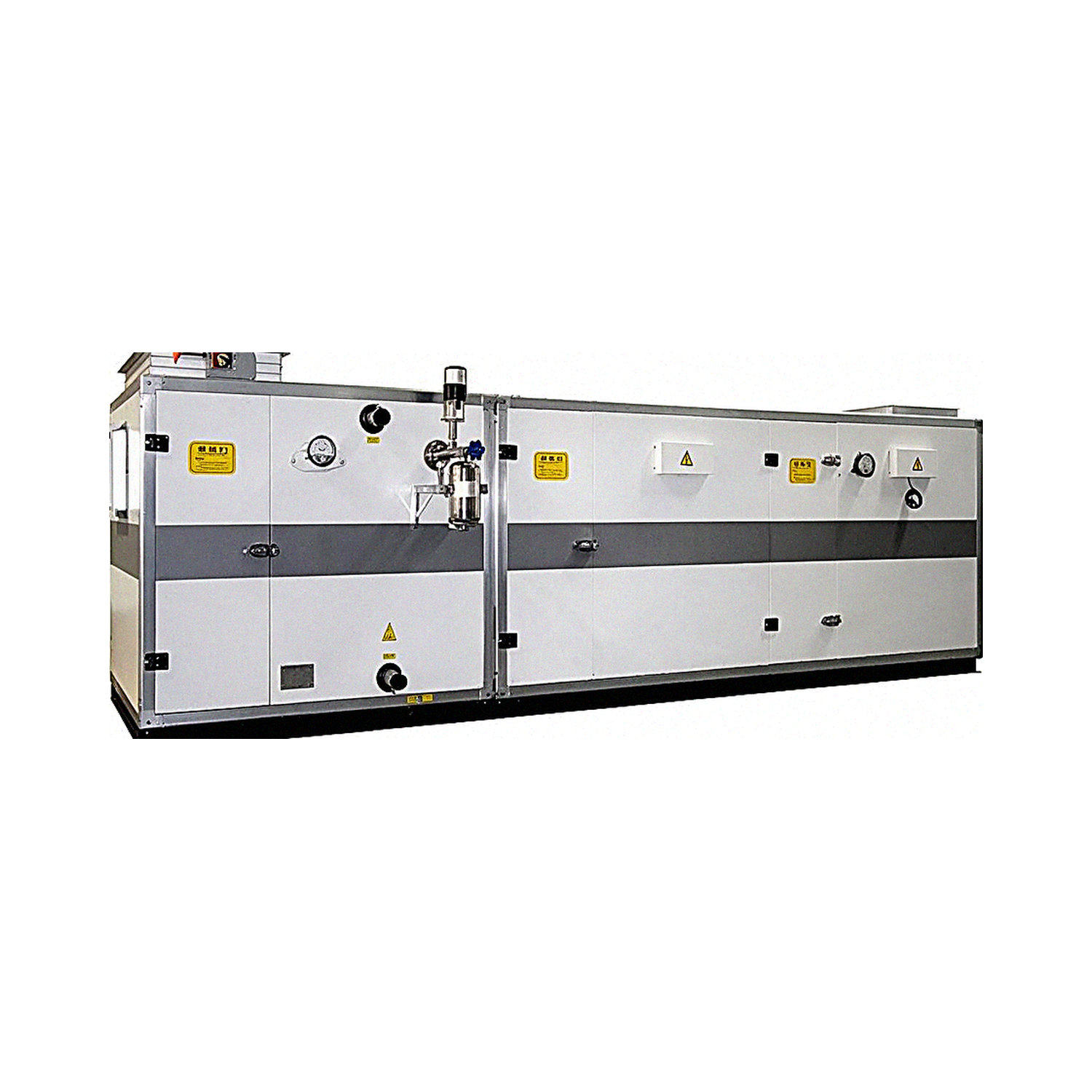
Purification Air Handling Unit
Unit advantages: Mortise-and-tenon sealed cabinet structure with bolted panel connections provides greater cabinet strength. The unit has a streamlined, attractive appearance and a clean, even interior. Its air leakage rate is only 50% of the standard limit, and it offers improved resistance to thermal bridging.
Patented design with a smooth, even interior surface that resists dust accumulation and microbial growth.
Users can select and combine functional sections such as fresh-air primary filtration, preheating, return air, hot-water coil, chilled-water coil, and fan sections. The following sections are described in detail:
Unit Construction
The cabinet uses a mortise-and-tenon labyrinth seal. The frame beams are closed-section aluminum profiles manufactured using specially designed roll-forming equipment. The inner and outer surfaces of the cabinet panels are made of color-coated steel or galvanized steel, with a protective film applied to the exterior. This gives the panels good resistance to bending and weathering, as well as resistance to corrosion and acids, alkalis, and salts; the color will not fade for 15 years. The interior is filled with flame-retardant insulation, greatly increasing the rigidity and corrosion resistance of the unit casing. Moisture does not reduce the insulation performance, so the unit maintains its thermal insulation and airtightness over time. The unit cabinet is reliably sealed.
The patented sealing structure meets the requirements of high-cleanliness air purification systems;
It eliminates thermal bridges and condensation, and also significantly reduces unit noise;
The aluminum alloy and structural steel profiles effectively increase panel strength.
Chilled-Water Coil (Hot-Water Coil) Section
The chilled-water coil (hot-water coil) section provides cooling, dehumidification, and droplet separation. It can also heat air using hot water below 65℃. A drain pan and condensate drain pipe are installed at the bottom.
The cooling coil (heat exchanger) is made using high-quality copper tubes and aluminum fins for air-conditioning applications. Mechanical tube expansion is completed in a single operation, ensuring tight contact between tubes and fins and high heat-transfer efficiency. The coil is easy to operate, maintain, and clean.
The fins are punched with double flanges to ensure uniform spacing. With factors such as air resistance, water resistance, fan motor power, and heat-transfer area taken into account, computer-aided optimization is used to determine the ideal fin spacing. The water circuit is designed to keep water velocity and the inlet-to-outlet water temperature difference within a reasonable range for heat exchangers of different sizes. This also fundamentally prevents water accumulation and air pockets inside the tubes. An automatic anti-siphon device is installed at the condensate outlet of the cooling coil, allowing condensate to drain smoothly under negative pressure and ensuring safe, effective operation. The fins are punched using high-speed presses from OAK, USA. The OAK oil applied during punching evaporates naturally after the fins are formed, leaving no oil residue. The fins do not carry water at the unit's standard operating air velocity.
The standard leak-test pressure is above 1.6MPa, and the maximum operating pressure is 1.6MPa.
In addition, the copper tube openings in the end plates are designed with a secondary flange, allowing the heat exchanger tubes to move freely during unit operation. This prevents tube cracking caused by water hammer or excessive thermal stress.

Fan Section
The unit uses low-noise, forward-curved centrifugal fans with double inlets, manufactured by designated air-conditioning fan manufacturers appointed by the Ministry of Machinery Industry. All fan impellers undergo dynamic balancing tests. The impeller shafts use low-noise ball bearings that require no lubrication maintenance and have a long service life. The fans feature low noise and good aerodynamic performance. The connection between the impeller and volute makes it easy to replace the impeller, bearings, and motor during maintenance. JG-type rubber shear vibration isolators are installed beneath the fan, reducing vibration and noise during operation.
The motor insulation class is B or F, and the ingress protection rating is IP54 or IP55. Motor cables are protected by high-strength protective conduits and connectors, providing reliable sealing and moisture resistance.

Filter Section
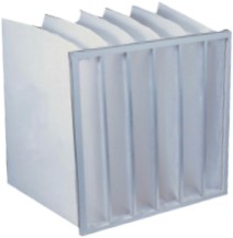
Depending on user requirements, the unit can be fitted with pre-filters, medium-efficiency filters, and high-efficiency filters. Units for general applications are fitted with pre-filters.
Pre-filters are generally panel-type filters. The filter frame is made of formed galvanized sheet steel, reinforced on both sides with formed galvanized steel mesh, and fitted with non-combustible filter media. Filtration efficiency: G3 (gravimetric efficiency ≥60%); initial pressure drop: 75Pa; final pressure drop: 150Pa. Filtration efficiency: F5 (counting efficiency 50%; depending on the filter media). Medium-efficiency filters can achieve filtration efficiency up to F9.

Dry Steam Humidification Section
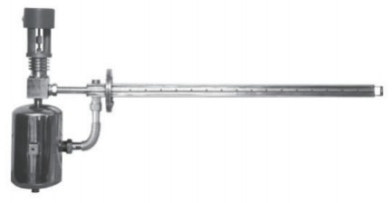
Humidification principle: A supply of saturated steam, reduced in pressure and filtered, is connected to the unit. The saturated steam flows laterally through the outer jacket of the double-layer spray pipe, then flows circumferentially into the elbow to preheat the central spray pipe. It passes through a baffle and enters the evaporation chamber. As the end face of the evaporation chamber suddenly increases in area, steam velocity decreases, separating the condensate contained in the saturated steam. The condensate is discharged through the outlet at the bottom of the evaporation chamber. The steam, now separated from the condensate, enters the preheated drying chamber. The chamber is filled with stainless steel media, which absorbs noise from the flowing steam and filters and separates moisture remaining in the steam. When the control valve opens, the pressure in the drying chamber drops and the vaporization temperature decreases. The moisture remaining in the steam is heated and vaporized again, completing the separation of steam and water from the saturated steam. The dry steam passes through the control valve into the central spray pipe and is discharged in the opposite direction through stainless steel silencing mesh openings into the airflow inside the air handling unit, humidifying the air.
Features:
Isothermal humidification with high humidification efficiency of over 95%.
Advanced steam-water separation technology imported from overseas ensures thorough separation, with no water spray.
The unique spray pipe design ensures that the dry steam is discharged without water spray or noise.

Unit Model Designation Guide

Determining the Left- or Right-Hand Configuration of the Air Handling Unit
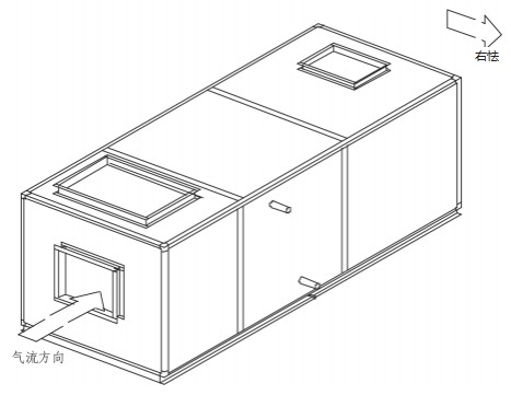
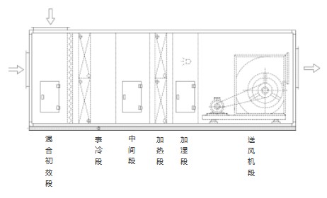
To determine the left- or right-hand configuration, stand facing the direction of airflow. If the water inlet and outlet pipes are on your left, the unit is left-hand; otherwise, it is right-hand. The unit shown below is right-hand.

Common Functional Section Combinations
Economy Combination:
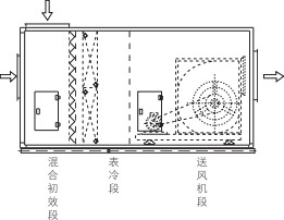
Mixing and pre-filter section, cooling coil section, fan supply section

General Process Combination:
Mixing and pre-filter section, cooling coil section, intermediate section, heating section, humidification section, supply fan section

Multifunctional Purification Combination:
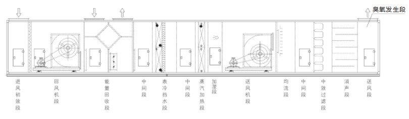
Inlet-air pre-filter section, return fan section, plate-type energy recovery section, intermediate section, cooling coil and moisture eliminator section, intermediate section, steam heating section, supply fan section, airflow equalizing section, medium-efficiency filter section, silencer section, supply fan section (ozone generator section)

Cooling capacity, water flow rate, and water pressure drop of the air handling unit
Return-air conditions: Inlet dry-bulb temperature 27℃, wet-bulb temperature 19 . 5℃, inlet water temperature 7℃, outlet water temperature 12℃.
Air Handling Unit Model | Four-row coil | Six-row coil | Eight-row coil |
Cooling capacity kW | Water flow rate m3/h | Water pressure drop kPa | Cooling capacity kW | Water flow rate m3/h | Water pressure drop kPa | Cooling capacity kW | Water flow rate m3/h | Water pressure drop kPa |
ZK- 01 | 6.63 | 1.14 | 7.8 | 8.15 | 1.40 | 12.8 | 9.62 | 1.65 | 13 |
ZK- 02 | 9.66 | 1.66 | 8.2 | 11.88 | 2.04 | 14 | 14.02 | 2.41 | 14.2 |
ZK- 03 | 17.5 | 3.01 | 8.2 | 21.6 | 3.71 | 14.3 | 25.7 | 4.42 | 14.3 |
ZK- 04 | 23.4 | 4.02 | 9.1 | 28.8 | 4.95 | 14.36 | 34.2 | 5.88 | 14.3 |
ZK- 05 | 29.1 | 5.00 | 9.8 | 35.5 | 6.10 | 17 | 43.4 | 7.46 | 17 |
ZK- 06 | 36.4 | 6.26 | 9.8 | 44.4 | 7.64 | 17 | 54.2 | 9.32 | 17 |
ZK |
| 47.3 | 8.13 | 9.8 | 57.7 | 9.92 | 17 | 70.5 | 12.12 | 17 |
ZK- 1 0 | 60.2 | 10.35 | 11.7 | 81.2 | 13.96 | 10.1 | 91.3 | 15.70 | 10.1 |
ZK- 1 5 | 87.7 | 15.08 | 7.2 | 107.8 | 18.54 | 12.1 | 121 | 20.81 | 12.1 |
ZK- 20 | 124.4 | 21.39 | 8.3 | 152.4 | 26.21 | 14.1 | 171.6 | 29.51 | 14.1 |
ZK- 25 | 152.4 | 26.21 | 10.2 | 197.6 | 33.98 | 11.8 | 222.2 | 38.21 | 11.8 |
ZK- 30 | 181.7 | 31.25 | 11 | 237.2 | 40.79 | 13.1 | 266.6 | 45.85 | 13.1 |
ZK | -35 | 195 | 33.53 | 13 | 256.3 | 44.08 | 12.3 | 288 | 49.53 | 12.3 |
ZK-40 | 208.6 | 35.87 | 12.9 | 275.4 | 47.36 | 15.7 | 309.3 | 53.19 | 15.7 |
ZK-45 | 246 | 42.30 | 13.4 | 304.5 | 52.36 | 16.7 | 350.4 | 60.26 | 16.7 |
ZK- 50 | 283.5 | 48.75 | 7.5 | 333.5 | 57.35 | 17 | 391.5 | 67.33 | 17 |
ZK- 60 | 340.2 | 58.50 | 7.5 | 400.2 | 68.82 | 17 | 469.8 | 80.79 | 17 |
ZK- 70 | 394.2 | 67.79 | 7.5 | 456.4 | 78.49 | 19.5 | 543.6 | 93.48 | 19.5 |
ZK |
| 448 | 77.04 | 8.5 | 521.5 | 89.68 | 19.5 | 617.4 | 106.17 | 19.5 |
ZK- 90 | 518.4 | 89.15 | 8.5 | 603.5 | 103.78 | 19.5 | 714.4 | 122.85 | 19.5 |
ZK- 1 00 | 588.8 | 101.26 | 8.5 | 685.4 | 117.87 | 19.5 | 811.4 | 139.54 | 19.5 |
ZK- 1 20 | 694.3 | 119.40 | 35.4 | 806.5 | 138.69 | 37.41 | 1050 | 180.57 | 38.9 |
ZK- 140 | 719.84 | 123.79 | 40 | 885.4 | 152.26 | 40.2 | 1044.8 | 179.67 | 41.2 |
ZK |
| 808.8 | 139.09 | 40.3 | 938.5 | 161.39 | 42.23 | 1221 | 209.97 | 44.5 |
ZK- 200 | 1108.2 | 190.58 | 62.1 | 1340.9 | 230.59 | 69.13 | 1745.6 | 300.19 | 70.23 |
Fresh-air conditions: Inlet dry-bulb temperature 35℃, wet-bulb temperature 28℃, inlet water temperature 7℃, outlet water temperature 12℃.
Air Handling Unit Model | Four-row coil | Six-row coil | Eight-row coil |
Cooling capacity kW | Water flow rate m3/h | Water pressure drop kPa | Cooling capacity kW | Water flow rate m3/h | Water pressure drop kPa | Cooling capacity kW | Water flow rate m3/h | Water pressure drop kPa |
ZK- 01 |
| 1.89 | 8.25 | 13.5 | 2.32 | 14.5 | 15.93 | 2.74 | 14.5 |
ZK- 02 | 22 . 44 | 3.86 | 9.3 | 27.6 | 4.75 | 16.2 | 32.57 | 5.60 | 15.8 |
ZK- 03 | 26 . 8 | 4.61 | 9.8 | 33 | 5.67 | 17.2 | 39.3 | 6.76 | 17.2 |
ZK- 04 | 35 . 7 | 6.14 | 10.9 | 44.1 | 7.58 | 17.2 | 52.3 | 8.99 | 17.2 |
ZK- 05 | 44 . 6 | 7.67 | 11.7 | 54.3 | 9.34 | 20.4 | 66.4 | 11.42 | 20.4 |
ZK- 06 | 55 . 7 | 9.58 | 11.7 | 67.9 | 11.68 | 20.4 | 82.9 | 14.26 | 20.4 |
ZK- 08 | 72 . 4 | 12.45 | 11.7 | 88.3 | 15.18 | 20.4 | 107.9 | 18.56 | 20.4 |
ZK- 1 0 | 92 . 1 | 15.84 | 14 | 124.2 | 21.36 | 12.1 | 139.7 | 24.02 | 12.1 |
ZK- 1 5 | 1 34 . 2 | 23.08 | 8.7 | 164.9 | 28.36 | 14.5 | 185.1 | 31.83 | 14.5 |
ZK- 20 | 1 90 . 3 | 32.73 | 9.9 | 233.2 | 40.10 | 16.9 | 272.5 | 46.86 | 16.9 |
ZK- 25 | 233 . 2 | 40.10 | 12.3 | 302.3 | 51.99 | 14.1 | 339.7 | 58.42 | 14.1 |
ZK | - 30 | 278 0 | 47.81 | 13.4 | 362.9 | 62.41 | 15.7 | 407.9 | 70.15 | 15.7 |
ZK- 35 | 298 4 | 51.32 | 15.6 | 392.1 | 67.43 | 14.8 | 440.6 | 75.77 | 14.8 |
ZK-40 | 31 9 . 2 | 54.89 | 15.5 | 421.4 | 72.47 | 18.9 | 473.2 | 81.38 | 18.9 |
ZK-45 | 376 . 4 | 64.73 | 16.1 | 465.9 | 80.12 | 20 | 536.1 | 92.19 | 20 |
ZK- 50 | 433 . 8 | 74.60 | 9 | 510.3 | 87.76 | 20.4 | 599 | 103.01 | 20.4 |
ZK- 60 | 520 . 5 | 89.51 | 9 | 612.3 | 105.30 | 20.4 | 718.8 | 123.61 | 20.4 |
ZK- 70 | 603 . 1 | 103.71 | 10.2 | 698.3 | 120.09 | 23.4 | 831.7 | 143.03 | 23.4 |
ZK- 80 | 685 . 4 | 117.87 | 10.2 | 797.9 | 137.21 | 23.4 | 944.6 | 162.44 | 23.4 |
ZK- 90 | 793 . 2 | 136.41 | 10.2 | 923.4 | 158.80 | 23.4 | 1093 | 187.96 | 23.4 |
ZK- 1 00 |
| 154.93 | 10.2 | 1048.7 | 180.34 | 23.4 | 1241.4 | 213.85 | 23.4 |
ZK- 1 20 | 1 042 . 3 | 179.24 | 42.1 | 1209.7 | 208.03 | 44.5 | 1575 | 270.85 | 39.6 |
ZK- 140 | 1 091 . 54 | 187.71 | 40 | 1342.6 | 230.89 | 40.2 | 1584.27 | 272.45 | 46.8 |
ZK- 1 60 | 1 21 3 . 5 | 208.68 | 46.8 | 1407.8 | 242.10 | 50.2 | 1832 | 315.13 | 51.5 |
ZK- 200 | 1 665 . 5 | 286.41 | 73.8 | 2011.3 | 345.88 | 82.2 | 2618.4 | 450.28 | 84.3 |
Heating capacity, water flow rate, and water pressure drop of the air handling unit
Return-air conditions: Inlet dry-bulb temperature 15℃, inlet water temperature 60℃, outlet water temperature 50℃
Air Handling Unit Model | Two-row coil | Four-row coil | Six-row coil |
Heating capacity kW | Water flow rate m3/h | Water pressure drop kPa | Heating capacity kW | Water flow rate m3/h | Water pressure drop kPa | Heating capacity kW | Water flow rate m3/h | Water pressure drop kPa |
ZK- 01 | 7.55 | 0.65 | 7.5 | 11.33 | 0.97 | 7.8 | 13.44 | 1.16 | 10.1 |
ZK- 02 | 11.8 | 1.01 | 8.1 | 17.71 | 1.52 | 8.2 | 21 | 1.81 | 10.2 |
ZK- 03 | 20.4 | 1.75 | 8.2 | 30.6 | 2.63 | 8.2 | 36.3 | 3.12 | 14.3 |
ZK- 04 | 27.74 | 2.39 | 9.1 | 40.8 | 3.51 | 9.1 | 47.2 | 4.06 | 14.3 |
ZK- 05 | 34.1 | 2.93 | 10.1 | 50.6 | 4.35 | 9.8 | 59.2 | 5.09 | 17 |
ZK- 06 | 40.7 | 3.50 | 11.4 | 62.1 | 5.34 | 9.8 | 75.2 | 6.47 | 17 |
ZK |
| 54.5 | 4.69 | 11.4 | 78.8 | 6.78 | 9.8 | 96.1 | 8.26 | 17 |
ZK |
| 67.1 | 5.77 | 10.5 | 99.8 | 8.58 | 11.7 | 124.8 | 10.73 | 10.1 |
ZK- 1 5 | 101.1 | 8.69 | 9.8 | 149.7 | 12.87 | 7.2 | 173.5 | 14.92 | 12.1 |
ZK- 20 | 135.6 | 11.66 | 9.8 | 199 | 17.11 | 8.3 | 248.8 | 21.39 | 14.1 |
ZK- 25 | 168.7 | 14.51 | 11.6 | 249.5 | 21.45 | 10.2 | 311.2 | 26.76 | 11.8 |
ZK- 30 | 202.6 | 17.42 | 11.8 | 304.5 | 26.18 | 11.2 | 380.9 | 32.75 | 13.1 |
ZK | - 35 | 236.4 | 20.33 | 12.5 | 356.6 | 30.66 | 13 | 444.3 | 38.20 | 12.3 |
ZK | - 40 | 270.4 | 23.25 | 12.4 | 399.2 | 34.33 | 12.9 | 480.8 | 41.34 | 15.7 |
ZK- 45 | 304.6 | 26.19 | 11.3 | 458.1 | 39.39 | 13.4 | 503.6 | 43.30 | 16.7 |
ZK- 50 | 337.3 | 29.00 | 10.4 | 512 | 44.02 | 7.5 | 553.8 | 47.62 | 17 |
ZK- 60 | 404.7 | 34.80 | 9.4 | 609.4 | 52.40 | 7.5 | 681.2 | 58.57 | 17 |
ZK- 70 | 472.4 | 40.62 | 10.3 | 699.1 | 60.11 | 8.8 | 783.7 | 67.39 | 19.5 |
ZK |
| 539.5 | 46.39 | 9.1 | 796 | 68.44 | 8.8 | 886.2 | 76.20 | 19.5 |
ZK- 90 | 606.8 | 52.18 | 9.1 | 883.8 | 75.99 | 8.5 | 996.9 | 85.72 | 19.5 |
ZK- 1 00 | 674.5 | 58.00 | 9.5 | 985.1 | 84.70 | 8.5 | 1127.6 | 96.96 | 19.5 |
ZK- 1 20 | 698.8 | 60.09 | 31.6 | 1048.4 | 90.15 | 8.5 | 1217.8 | 104.71 | 34.34 |
ZK- 140 | 746.26 | 64.17 | 40 | 1119.39 | 96.25 | 32.5 | 1327.6 | 114.15 | 37.8 |
ZK |
| 814.2 | 70.01 | 35.2 | 1221.3 | 105.01 | 33.6 | 1417.1 | 121.85 | 38.77 |
ZK- 200 | 1115.5 | 95.92 | 42.6 | 1673.2 | 143.87 | 37 | 2024.7 | 174.09 | 63.46 |
Fresh-air conditions: Inlet dry-bulb temperature 7℃, inlet water temperature 60℃, outlet water temperature 50℃
Air Handling Unit Model | Two-row coil | Four-row coil | Six-row coil |
Heating capacity kW | Water flow rate m3/h | Water pressure drop kPa | Heating capacity kW | Water flow rate m3/h | Water pressure drop kPa | Heating capacity kW | Water flow rate m3/h | Water pressure drop kPa |
ZK- 01 | 11.55 | 0.99 | 8.2 | 17.22 | 1.48 | 8.5 | 20.54 | 1.77 | 12.3 |
ZK- 02 | 18.05 | 1.55 | 9.3 | 26.91 | 2.31 | 9.6 | 32.09 | 2.76 | 15.6 |
ZK- 03 | 31.2 | 2.68 | 9.8 | 46.8 | 4.02 | 9.8 | 55.5 | 4.77 | 17.2 |
ZK- 04 | 41.9 | 3.60 | 10.9 | 62.4 | 5.37 | 10.9 | 72.2 | 6.21 | 17.2 |
ZK- 05 | 52.2 | 4.49 | 12.1 | 77.4 | 6.66 | 11.7 | 90.6 | 7.79 | 20.4 |
ZK- 06 | 62.3 | 5.36 | 13.7 | 95 | 8.17 | 11.7 | 115.1 | 9.90 | 20.4 |
ZK |
| 83.4 | 7.17 | 13.7 | 120.6 | 10.37 | 11.7 | 147 | 12.64 | 20.4 |
ZK- 1 0 | 102.7 | 8.83 | 12.6 | 152.7 | 13.13 | 14 | 190.9 | 16.41 | 12.1 |
ZK- 1 5 | 154.7 | 13.30 | 11.8 | 229 | 19.69 | 8.7 | 265.5 | 22.83 | 14.5 |
ZK- 20 | 207.5 | 17.84 | 11.8 | 304.5 | 26.18 | 9.9 | 380.7 | 32.73 | 16.9 |
ZK- 25 | 258.1 | 22.19 | 13.9 | 381.7 | 32.82 | 12.3 | 476.1 | 40.94 | 14.1 |
ZK- 30 | 310 | 26.66 | 14.2 | 465.9 | 40.06 | 13.4 | 582.8 | 50.11 | 15.7 |
ZK | - 35 | 361.7 | 31.10 | 15 | 545.6 | 46.91 | 15.6 | 679.8 | 58.45 | 14.8 |
ZK- 40 | 413.7 | 35.57 | 14.9 | 610.8 | 52.52 | 15.5 | 735.6 | 63.25 | 18.9 |
ZK- 45 | 466 | 40.07 | 13.96 | 700.9 | 60.27 | 16.1 | 770.5 | 66.25 | 20 |
ZK- 50 | 516.1 | 44.38 | 12.5 | 783.4 | 67.36 | 9 | 847.3 | 72.85 | 20.4 |
ZK- 60 | 619.2 | 53.24 | 11.3 | 932.4 | 80.17 | 9 | 1042.2 | 89.61 | 20.4 |
ZK- 70 | 722.8 | 62.15 | 12.4 | 1069.6 | 91.97 | 10.2 | 1199.1 | 103.1 | 23.4 |
ZK |
| 825.4 | 70.97 | 10.9 | 1217.9 | 104.72 | 10.2 | 1355.9 | 116.59 | 23.4 |
ZK- 90 | 928.4 | 79.83 | 10.9 | 1352.2 | 116.27 | 10.2 | 1525.3 | 131.15 | 23.4 |
ZK- 1 00 | 1032 | 88.74 | 11.4 | 1507.2 | 129.6 | 10.2 | 1725.2 | 148.34 | 23.4 |
ZK- 1 20 | 1048.4 | 90.15 | 37.8 | 1572.6 | 135.22 | 38.6 | 1826.7 | 157.07 | 40.8 |
ZK- 140 | 1141.03 | 98.11 | 40 | 1701.48 | 146.3 | 40.5 | 2028.57 | 174.43 | 42.6 |
ZK |
| 1221.2 | 105.0 | 43.5 | 1831.9 | 157.52 | 44.1 | 2125.6 | 182.77 | 46.1 |
ZK- 200 | 1673.2 | 143.87 | 62.2 | 2509.8 | 215.8 | 51.1 | 3037.2 | 261.15 | 75.5 |
Steam heating capacity of the air handling unit
Air-conditioning conditions: Inlet dry-bulb temperature 15℃
Air handling unit model | Coil rows Two-row coil Three-row coil |
Steam pressure | Steam pressure | Steam pressure |
0 1 Mpa | 0 2Mpa | 0 3Mpa | 0 4Mpa | 0 1 Mpa | 0 2Mpa | 0 3Mpa | 0 4Mpa | 0 1 Mpa | 0 2Mpa | 0 3Mpa | 0 4Mpa |
ZK- 01 | 5.8 | 7.25 | 7.83 | 8.7 | 15.8 | 19.75 | 21.33 | 23.7 | 20.3 | 25.38 | 27.41 | 30.45 |
ZK- 02 | 14.6 | 18.25 | 19.71 | 21.9 | 21.8 | 27.25 | 29.43 | 32.7 | 32.6 | 40.75 | 44.01 | 48.9 |
ZK- 03 | 16.2 | 20.30 | 22.00 | 24.5 | 28.2 | 39.50 | 43.00 | 47.8 | 45.4 | 56.7 | 61.70 | 68.6 |
ZK- 04 | 23 | 27.40 | 30.60 | 33.3 | 44.8 | 53.40 | 59.80 | 64.9 | 64.3 | 76.7 | 85.80 | 93.2 |
ZK- 05 | 27.7 | 33.40 | 36.10 | 40.3 | 54.1 | 65.10 | 70.40 | 78.5 | 77.7 | 93.5 | 101.10 | 112.7 |
ZK- 06 | 33.6 | 40.40 | 43.70 | 48.6 | 65.5 | 78.70 | 85.20 | 94.8 | 94.1 | 113 | 122.40 | 136 |
ZK- 08 | 44.4 | 53.70 | 58.20 | 64.9 | 86.6 | 104.60 | 113.60 | 126.5 | 124.4 | 150.2 | 163.10 | 181.7 |
ZK- 1 0 | 56.5 | 68.90 | 74.70 | 83.2 | 110.2 | 134.40 | 145.70 | 162.2 | 158.3 | 193 | 209.20 | 233 |
ZK- 1 5 | 84.6 | 103.00 | 111.60 | 124.2 | 164.9 | 200.80 | 217.50 | 242.2 | 236.8 | 288.3 | 312.30 | 347.8 |
ZK- 20 | 112.1 | 135.90 | 147.30 | 163.9 | 218.7 | 265.00 | 287.10 | 319.7 | 314 | 380.5 | 412.30 | 459 |
ZK- 25 | 146 | 176.90 | 191.70 | 213.4 | 284.7 | 344.90 | 373.80 | 416.1 | 408.8 | 495.3 | 536.70 | 597.5 |
ZK- 30 | 170.3 | 206.40 | 223.50 | 248.2 | 332.2 | 402.40 | 435.90 | 484 | 477 | 577.8 | 625.90 | 694.9 |
ZK- 35 | 201.7 | 244.30 | 264.70 | 294.8 | 393.2 | 476.40 | 516.30 | 574.8 | 564.6 | 684 | 741.30 | 825.3 |
ZK-40 | 233 | 282.30 | 305.80 | 340.6 | 454.4 | 550.40 | 596.40 | 664.1 | 652.5 | 790.3 | 856.40 | 953.6 |
ZK-45 | 260.7 | 315.80 | 342.10 | 381 | 508.3 | 615.80 | 667.20 | 742.9 | 729.9 | 884.2 | 958.00 | 1066.7 |
ZK- 50 | 305.6 | 349.30 | 379.50 | 421.4 | 595.8 | 681.20 | 738.00 | 821.7 | 855.6 | 978.1 | 1059.80 | 1179.9 |
ZK- 60 | 335.6 | 406.60 | 440.60 | 490.5 | 654.4 | 792.80 | 859.10 | 956.4 | 939.7 | 1138.4 | 1233.60 | 1373.3 |
ZK- 70 | 392.6 | 475.70 | 515.40 | 573.9 | 765.6 | 927.60 | 1005.00 | 1119 | 1099.4 | 1332 | 1443.10 | 1606.8 |
ZK- 80 | 449.7 | 544.90 | 590.40 | 657.3 | 876.9 | 1062.60 | 1151.30 | 1281.8 | 1259.2 | 1525.7 | 1653.10 | 1840.5 |
ZK- 90 | 513.6 | 622.20 | 674.10 | 750.6 | 1001.6 | 1213.30 | 1314.60 | 1463.7 | 1438.1 | 1742.2 | 1887.60 | 2101.8 |
ZK- 1 00 | 577.4 | 699.50 | 758.00 | 843.9 | 1126 | 1364.00 | 1478.00 | 1645.6 | 1616.8 | 1958.6 | 2122.30 | 2362.9 |
ZK- 1 20 | 664.1 | 804.40 | 871.70 | 970.4 | 1294.5 | 1568.60 | 1698.50 | 1891.7 | 1858.5 | 2252.5 | 2440.10 | 3716.6 |
ZK- 1 40 | 702.4 | 878.00 | 948.24 | 1053.6 | 1356.3 | 1695.40 | 1831.05 | 2034.5 | 1989.6 | 2487 | 2685.96 | 2984.4 |
ZK- 1 60 | 763.3 | 925.00 | 1002.50 | 1116.1 | 1489.2 | 1803.80 | 1954.50 | 2175.5 | 2137.2 | 2590.6 | 2806.80 | 3125.1 |
ZK- 200 | 878.2 | 1063.80 | 1152.50 | 1283.5 | 1712.1 | 2074.40 | 2247.50 | 2501.8 | 2457.8 | 2978.8 | 3227.80 | 3592.5 |
Fresh-air conditions: Inlet dry-bulb temperature 7℃
Air Handling Unit Model | Coil rows Two-row coil Three-row coil |
Steam pressure | Steam pressure | Steam pressure |
0 . 1 Mpa | 0 . 2Mpa | 0 . 3Mpa | 0 . 4Mpa | 0 . 1 Mpa | 0 . 2Mpa | 0 . 3Mpa | 0 . 4Mpa | 0 . 1 Mpa | 0 . 2Mpa | 0 . 3Mpa | 0 . 4Mpa |
ZK- 01 | 12.6 | 15.75 | 17.01 | 18.9 | 14.5 | 18.13 | 19.58 | 21.75 | 20.6 | 25.75 | 27.81 | 30.9 |
ZK- 02 | 18.6 | 23.25 | 25.11 | 27.9 | 22.6 | 28.28 | 30.51 | 33.9 | 40.5 | 50.63 | 54.68 | 60.75 |
ZK- 03 | 21.9 | 27.30 | 29.80 | 33.1 | 37.1 | 47.60 | 51.80 | 57.5 | 54.7 | 68.4 | 74.40 | 82.7 |
ZK- 04 | 31 | 37.00 | 41.40 | 44.9 | 53.9 | 64.40 | 72.00 | 78.2 | 77.5 | 92.5 | 103.40 | 112.4 |
ZK- 05 | 37.5 | 45.10 | 48.70 | 54.3 | 65.2 | 78.40 | 84.80 | 94.6 | 93.6 | 112.7 | 121.90 | 135.9 |
ZK- 06 | 45.4 | 54.50 | 59.00 | 65.7 | 78.9 | 94.80 | 102.70 | 114.2 | 113.4 | 136.2 | 147.50 | 164.1 |
ZK- 08 | 59.9 | 72.40 | 78.60 | 87.6 | 104.3 | 126.00 | 136.70 | 152.3 | 149.39 | 181 | 196.40 | 218.9 |
ZK- 1 0 | 76.2 | 93.00 | 100.80 | 112.2 | 132.7 | 161.80 | 175.40 | 195.3 | 190.6 | 232.5 | 252.00 | 280.6 |
ZK- 1 5 | 114.2 | 139.00 | 150.60 | 167.7 | 198.6 | 241.90 | 262.00 | 291.7 | 285.4 | 347.5 | 376.50 | 419.1 |
ZK- 20 | 151.4 | 183.50 | 198.80 | 221.4 | 263.5 | 319.30 | 346.00 | 385.2 | 378.6 | 458.8 | 497.31 | 553.4 |
ZK- 25 | 197.1 | 238.80 | 258.80 | 277.1 | 343 | 415.50 | 450.30 | 501.3 | 492.8 | 597 | 646.90 | 720.2 |
ZK- 30 | 230 | 278.60 | 301.80 | 335.1 | 400.2 | 484.70 | 525.10 | 583 | 574.9 | 696.5 | 754.50 | 837.6 |
ZK- 35 | 272.2 | 329.80 | 345.70 | 397.9 | 473.7 | 573.80 | 621.90 | 692.4 | 680.6 | 824.5 | 893.50 | 994.8 |
ZK-40 | 314.6 | 381.00 | 412.70 | 459.7 | 547.4 | 662.90 | 718.40 | 799.9 | 786.4 | 952.5 | 1032.10 | 1149.3 |
ZK- 45 | 351.9 | 426.30 | 461.88 | 514.3 | 612.3 | 741.80 | 803.60 | 894.8 | 879.7 | 1065.8 | 1154.60 | 1285.7 |
ZK- 50 | 412.5 | 471.60 | 511.00 | 568.9 | 717.8 | 820.60 | 889.10 | 989.9 | 1031.36 | 1179 | 1277.40 | 1422.2 |
ZK- 60 | 453.1 | 548.90 | 594.80 | 662.2 | 788.3 | 955.40 | 1034.90 | 1152.2 | 1232.7 | 1372.3 | 1487.00 | 1655.4 |
ZK- 70 | 530.1 | 642.30 | 695.80 | 774.8 | 922.4 | 1117.05 | 1210.70 | 1348.1 | 1325.3 | 1605.6 | 1739.50 | 1936.9 |
ZK- 80 | 607.1 | 735.60 | 797.00 | 887.4 | 1056.4 | 1279.90 | 1386.80 | 1544 | 1517.8 | 1839 | 1992.60 | 2218.4 |
ZK- 90 | 693.4 | 840.00 | 910.10 | 1013.3 | 1206.5 | 1461.50 | 1583.50 | 1763.2 | 1733.4 | 2099.9 | 2275.10 | 2533.3 |
ZK- 1 00 | 779.5 | 944.30 | 1023.20 | 1139.2 | 1356.4 | 1643.10 | 1780.40 | 1982.2 | 1948.8 | 2360.8 | 2558.10 | 2848 |
ZK- 1 20 | 919.4 | 1085.50 | 1177.50 | 1310.1 | 1560.5 | 1888.00 | 2047.50 | 2779.6 | 2241.3 | 2714.5 | 2941.50 | 3275.2 |
ZK- 1 40 | 993.1 | 1241.40 | 1340.69 | 1498.65 | 1676.4 | 2108.13 | 2276.78 | 2529.75 | 2345.8 | 2946 | 3181.68 | 3535.2 |
ZK- 1 60 | 1057.2 | 1245.30 | 1352.60 | 1506.5 | 1793.5 | 2173.50 | 2354.50 | 2621.5 | 2577.3 | 3122.6 | 3383.10 | 3766.6 |
ZK- 200 | 1215.9 | 1436.50 | 1556.50 | 1732.5 | 2062.5 | 2500.50 | 2707.50 | 3014.6 | 2964.5 | 3590.8 | 3890.50 | 4331.5 |
Reference motor power selection table for air handling unit fans
38
1. The selected fan may be replaced; actual power is subject to the rating shown on the unit nameplate.
2. Fan total pressure can be changed according to design requirements.
3. A reduced-voltage starter should be used when motor power is ≥11kw.
4. Italicized entries indicate optional external rotor fans.
5. In the table, 22大2 represents two 22kw fans.
Air resistance calculations for each functional section of the air handling unit
Functional Section Name | Category | Air Resistance pa |
Mixing Section | Fresh Air/Return Air Mixing | 20 |
Fresh Air/Exhaust Air Mixing | 20 |
Primary-Efficiency Panel Filter Section | G3 | 50 |
Primary-Efficiency Bag Filter Section | G4 | 70 |
Medium-Efficiency Bag Filter Section | F6 | 120 |
Sub-HEPA Filter Section | F9 | 200 |
High-Efficiency Filter Section | H13 | 300 |
Cooling Coil Section | 2 Rows | 70 |
4 Rows | 110 |
6 Rows | 145 |
8 Rows | 180 |
Steam Heating Section | 1 Row | 40 |
2 Rows | 60 |
3 Rows | 80 |
Functional Section Name | Category | Air Resistance pa |
Heating Section | 2 Rows | 70 |
4 Rows | 110 |
6 Rows | 145 |
Energy Recovery Section | Panel Type | 140 |
Rotary Wheel Type | 170 |
Heat Pipe Type | 110 |
Sound Attenuation Section | Resistive Type | 25 |
Microperforated Type | 30 |
Supply Air Section |
| 10 |
Intermediate Section |
| 10 |
Fan Section |
| 10 |
Drift Eliminator |
| 35 |
Airflow Equalizing Section |
| 30 |
Electric Heating Section |
| 20 |
Unit airflow and dimensions table
Modular Model |
Reference Airflow | Coil Face
Area (ft²) | Coil Face Velocity |
2m/s | 2.25m/s | 2.5m/s | 2.75m/s | 3m/s | 3.25m/s | 3.5m/s | 4m/s |
zk0102 | 1000~1200 | 0.09335 | 672 | 756 | 840 | 924 | 1008 | 1092 | 1176 | 1344 |
zk0202 | 1500~2500 | 0.2267 | 1632 | 1836 | 2040 | 2244 | 2448 | 2652 | 2856 | 3264 |
zk0203 | 2500~4500 | 0.3994 | 2876 | 3235 | 3595 | 3954 | 4314 | 4673 | 5032 | 5751 |
zk0303 | 4500~7500 | 0.6344 | 4568 | 5139 | 5710 | 6281 | 6852 | 7422 | 7993 | 9135 |
zk0304 | 7500~10000 | 0.9087 | 6543 | 7360 | 8178 | 8996 | 9814 | 10632 | 11450 | 13085 |
zk0404 | 10000~14000 | 1.2116 | 8724 | 9814 | 10904 | 11995 | 13085 | 14176 | 15266 | 17447 |
zk0405 | 14000~18000 | 1.5773 | 11357 | 12776 | 14196 | 15615 | 17035 | 18454 | 19874 | 22713 |
zk0505 | 18000~25000 | 2.0593 | 14827 | 16680 | 18534 | 20387 | 22240 | 24094 | 25947 | 29654 |
zk0506 | 25000~30000 | 2.5368 | 18265 | 20548 | 22831 | 25114 | 27397 | 29681 | 31964 | 36530 |
zk0606 | 28000~34000 | 2.9147 | 20986 | 23609 | 26232 | 28856 | 31479 | 34102 | 36725 | 41972 |
zk0607 | 30000~41000 | 3.5135 | 25297 | 28459 | 31622 | 34784 | 37946 | 41108 | 44270 | 50594 |
zk0707 | 38000~48000 | 4.1245 | 29696 | 33408 | 37121 | 40833 | 44545 | 48257 | 51969 | 59393 |
zk0708 | 45000~56000 | 4.7812 | 34425 | 38728 | 43031 | 47334 | 51637 | 55940 | 60243 | 68849 |
zk0808 | 50000~65000 | 5.4895 | 39524 | 44465 | 49406 | 54346 | 59287 | 64227 | 69168 | 79049 |
zk0809 | 60000~73000 | 6.2434 | 44952 | 50572 | 56191 | 61810 | 67429 | 73048 | 78667 | 89905 |
zk0909 | 70000~81000 | 6.9483 | 50028 | 56281 | 62535 | 68788 | 75042 | 81295 | 87549 | 100056 |
zk0910 | 75000~91000 | 7.7873 | 56069 | 63077 | 70086 | 77094 | 84103 | 91111 | 98120 | 112137 |
zk1010 | 80000~100000 | 8.322 | 59918 | 67408 | 74898 | 82388 | 89878 | 97367 | 104857 | 119837 |
zk1011 | 90000~110000 | 9.234 | 66485 | 74795 | 83106 | 91417 | 99727 | 108038 | 116348 | 132970 |
zk1111 | 100000~132000 | 10.8767 | 78312 | 88101 | 87890 | 107679 | 117468 | 127257 | 137046 | 156624 |
zk1113 | 120000~158000 | 12.8723 | 92681 | 104266 | 115851 | 127436 | 139021 | 150606 | 162191 | 185361 |
zk1115 | 150000~180000 | 14.7448 | 106163 | 119433 | 132703 | 145974 | 159244 | 172514 | 185784 | 212325 |
zk1117 | 180000~200000 | 16.2792 | 117210 | 131862 | 146513 | 161164 | 175815 | 190467 | 205118 | 234420 |
Modular cross-sectional dimensions and unit modules for modular air handling units
Unit height = height module X320 + 2 × panel thickness + 100/120 (base)
Unit width = width module X320 + 2 × panel thickness; unit length = total length modules of all functional sections X100
Reference Airflow m3/h | Standard Module Value | Cross-Section Dimensions |
Height | Width | Height | Width |
1000~1200 | 01 | 02 | 500 | 720 |
1500~2500 | 02 | 02 | 820 | 720 |
2500~4500 | 02 | 03 | 820 | 1040 |
4500~7500 | 03 | 03 | 1140 | 1040 |
7500~10000 | 03 | 04 | 1140 | 1360 |
10000~14000 | 04 | 04 | 1460 | 1360 |
14000~18000 | 04 | 05 | 1460 | 1680 |
18000~25000 | 05 | 05 | 1780 | 1680 |
25000~30000 | 05 | 06 | 1780 | 2000 |
28000~34000 | 06 | 06 | 2100 | 2000 |
30000~41000 | 06 | 07 | 2160 | 2360 |
38000~48000 | 07 | 07 | 2480 | 2360 |
45000~56000 | 07 | 08 | 2480 | 2680 |
50000~65000 | 08 | 08 | 2800 | 2680 |
| 60000~73000 | 08 | 09 | 2800 | 3000 |
70000~81000 | 09 | 09 | 3120 | 3000 |
75000~91000 | 09 | 10 | 3120 | 3320 |
80000~100000 | 10 | 10 | 3440 | 3320 |
| 90000~110000 | 10 | 11 | 3440 | 3640 |
100000~132000 | 11 | 11 | 3760 | 3640 |
| 120000~158000 | 11 | 13 | 3760 | 4280 |
150000~180000 | 11 | 15 | 3760 | 4920 |
180000~200000 | 11 | 17 | 3760 | 5560 |
Note: 1. Unit height H includes the unit base. Unit length is determined by the combined lengths of the configured functional sections.
2. If the required unit cross-sectional dimensions do not match the table above, a custom design can be provided according to user requirements.
3. Air handling unit models can be selected by referring to the airflow corresponding to the modules in the table above.
4. For units with a module size of 0607 or larger, the base is 120 and the default panel thickness is 50.
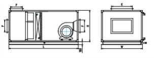
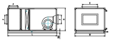
Standard Drawings for Small Units I
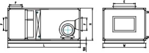
Standard combined unit: mixing section + bag filter section + cooling coil and moisture eliminator section + horizontal supply fan section

|
| Standard Modular Unit |
|
|
Unit | L (Length) | w (Width) | H (Height) | E | F |
zk0202 | 2200 | 720 | 720 | 320 | 200 |
zk0203 | 2200 | 1040 | 720 | 400 | 320 |
zk0303 | 2400 | 1040 | 1040 | 400 | 400 |
zk0304 | 2400 | 1360 | 1040 | 630 | 400 |
|
|
|
|
|
|
zk0404 | 3200 | 1360 | 1360 | 630 | 500 |
zk0405 | 3200 | 1680 | 1360 | 800 | 630 |
zk0505 | 3400 | 1680 | 1680 | 1000 | 630 |
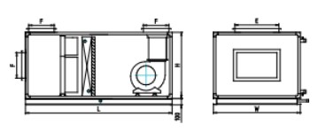
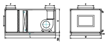
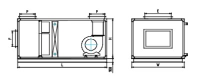
Standard combined unit Type I: mixing section + bag filter section + cooling coil and moisture eliminator section + top supply fan section

Standard Modular Unit | Type |
Unit | L (Length) | w (Width) | H (Height) | E | F |
zk0202 | | 2200 | 720 | 720 | 320 | 200 |
zk0203 | | 2200 | 1040 | 720 | 400 | 320 |
zk0303 | | 2400 | 1040 | 1040 | 400 | 400 |
zk0304 | | 2400 | 1360 | 1040 | 630 | 400 |
zk0404 | | 3200 | 1360 | 1360 | 630 | 500 |
zk0405 | | 3300 | 1680 | 1360 | 800 | 630 |
zk0505 | | 3700 | 1680 | 1680 | 1000 | 630 |
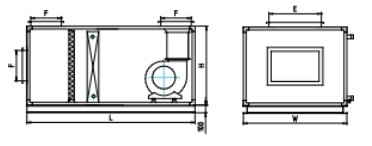
Standard combined unit Type II: mixing section + panel filter section + cooling coil and moisture eliminator section + horizontal supply fan section

Standard Modular Unit || Type |
Unit | L (Length) | w (Width) | H (Height) | E | F |
zk0202 || | 2000 | 720 | 720 | 320 | 200 |
zk0203 || | 2000 | 1040 | 720 | 400 | 320 |
zk0303 || | 2200 | 1040 | 1040 | 400 | 400 |
zk0304 || | 2200 | 1360 | 1040 | 630 | 400 |
zk0404 || | 3000 | 1360 | 1360 | 630 | 500 |
zk0405 || | 3000 | 1680 | 1360 | 800 | 630 |
zk0505 || | 3200 | 1680 | 1680 | 1000 | 630 |
Standard combined unit Type III: mixing section + panel filter section + cooling coil and moisture eliminator section + top supply fan section

Standard Modular Unit ||| Type |
Unit | L (Length) | w (Width) | H (Height) | E | F |
zk0202 ||| | 2000 | 720 | 720 | 320 | 200 |
zk0203 ||| | 2000 | 1040 | 720 | 400 | 320 |
zk0303 ||| | 2200 | 1040 | 1040 | 400 | 400 |
zk0304 ||| | 2200 | 1360 | 1040 | 630 | 400 |
zk0404 ||| | 3000 | 1360 | 1360 | 630 | 500 |
zk0405 ||| | 3100 | 1680 | 1360 | 800 | 630 |
zk0505 ||| | 3400 | 1680 | 1680 | 1000 | 630 |
Standard Drawings for Small Units II
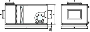
Standard combined unit Type IV: mixing section + panel filter section + steam heating section + horizontal supply fan section

Standard Modular Unit |v Type |
Unit | L (Length) | w (Width) | H (Height) | E | F |
zk0202 |v | 1600 | 720 | 720 | 320 | 200 |
zk0203 |v | 1600 | 1040 | 720 | 400 | 320 |
zk0303 |v | 1800 | 1040 | 1040 | 400 | 400 |
zk0304 |v | 1800 | 1360 | 1040 | 630 | 400 |
zk0404 |v | 2600 | 1360 | 1360 | 630 | 500 |
zk0405 |v | 2600 | 1680 | 1360 | 800 | 630 |
zk0505 |v | 2800 | 1680 | 1680 | 1000 | 630 |
Standard combined unit Type V: mixing section + panel filter section + steam heating section + top supply fan section

Standard Modular Unit v Type |
Unit | L (Length) | w (Width) | H (Height) | E | F |
zk0202 v | 1600 | 720 | 720 | 320 | 200 |
zk0203 v | 1600 | 1040 | 720 | 400 | 320 |
zk0303 v | 1800 | 1040 | 1040 | 400 | 400 |
zk0304 v | 1800 | 1360 | 1040 | 630 | 400 |
zk0404 v | 2600 | 1360 | 1360 | 630 | 500 |
zk0405 v | 2700 | 1680 | 1360 | 800 | 630 |
zk0505 v | 3000 | 1680 | 1680 | 1000 | 630 |
Standard combined unit Type VI: mixing section + bag filter section + steam heating section + horizontal supply fan section

Standard Modular Unit v| Type |
Unit | L (Length) | w (Width) | H (Height) | E | F |
zk0202 v| | 1800 | 720 | 720 | 320 | 200 |
zk0203 v| | 1800 | 1040 | 720 | 400 | 320 |
zk0303 v| | 2000 | 1040 | 1040 | 400 | 400 |
zk0304 v| | 2000 | 1360 | 1040 | 630 | 400 |
zk0404 v| | 2800 | 1360 | 1360 | 630 | 500 |
zk0405 v| | 2800 | 1680 | 1360 | 800 | 630 |
zk0505 v| | 3000 | 1680 | 1680 | 1000 | 630 |
Standard combined unit Type VII: mixing section + bag filter section + steam heating section + top supply fan section

Standard Modular Unit v|| Type |
Unit L (Length) w (Width) H (Height) E F |
zk0202 v|| 1800 720 720 320 200 |
zk0203 v|| 1800 1040 720 400 320 |
zk0303 v|| 2000 1040 1040 400 400 |
zk0304 v|| 2000 1360 1040 630 400 |
zk0404 v|| 2800 1360 1360 630 500 |
zk0405 v|| 2900 1680 1360 800 630 |
zk0505 v|| 3200 1680 1680 1000 630 |
Functional Diagram
No. |
Name |
Length Dimension Module (N: Standard Module Value 100) |
Remarks |
|
Mixing Section | ZK0102~ZK0203:4N ZK0303~ZK0304:5N ZK0404~ZK0405:6N ZK0505~ZK0707:7N ZK0708~ZK0809:9N ZK0909~ZK1113:11N ZK1115~ZK1117:13N ZK1121:17N |
|
|
Fresh Air/Exhaust Air Section | ZK0202~ZK0505:13N ZK0506~ZK0606:17N ZK0607~ZK0707:18N ZK0707~ZK0809:21N ZK_0909~ZK1113:25N ZK1115~ZK1115:30N ZK1117:37N |
|
3 |
Intermediate Section |
6N |
|
4 |
Panel Filter Section |
2N | An access section is recommended upstream of this functional section. |
|
Bag Filter Section |
ZK0102~ZK0505:6N ZK0506~ZK1117:6N | An access section is recommended upstream of this functional section. |
|
Primary and Medium-Efficiency Filter Section |
6N | An access section is recommended upstream of this functional section. |
|
Cooling Coil and Drift Eliminator Section | ZK0202~ZK0707:7N ZK0708~ZK1111:8N ZK1113~ZK1117:10N | Same dimensions as the direct-drain wet media humidifier |
|
Cooling Coil Circulating-Water Wet Media Humidification Section | ZK0202~ZK0707:9N ZK0708~ZK1111:10N ZK1113~ZK1117:12N |
|
|
Heating Section |
3N |
|
|
Dry Steam Humidification Section |
6N |
|
|
Wet Media Humidification Section |
| Installed in combination with the coil; occupies no additional space. |
1 2 |
High-Pressure Spray (Micro) Fog Humidification Section |
6N | A wet media drift eliminator is required. |
1 3 |
Sound Attenuator Section |
8N丶14N丶9N | Supplied as 8N unless otherwise specified. |
1 4 | Airflow Equalizing Section |
7N |
|
15 | Fan Section |
See Fan Section |
|
Technical Performance and Overall Dimensions of Air Handling Unit Functional Sections
Mixing section, inlet section, supply air section
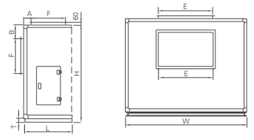
The mixing section mixes primary return air with fresh air. Unless otherwise specified, the unit is not supplied with an airflow control damper. An access door is provided.
Removing the air outlet from the cross-section or top of the mixing section creates a typical inlet or supply air section.

Model Size | H | w | L | A | B | E | F | T |
ZK0102 | 500 | 720 | 500 | 50 | 100 | 200 | 200 | 100 |
ZK0202 | 820 | 720 | 500 | 50 | 260 | 320 | 200 | 100 |
ZK0203 | 820 | 1040 | 500 | 50 | 200 | 400 | 320 | 100 |
ZK0303 | 1140 | 1040 | 600 | 50 | 320 | 400 | 400 | 100 |
ZK0304 | 1140 | 1360 | 600 | 50 | 320 | 630 | 400 | 100 |
ZK0404 | 1460 | 1360 | 600 | 50 | 430 | 630 | 500 | 100 |
ZK0405 | 1460 | 1680 | 600 | 50 | 365 | 1000 | 500 | 100 |
ZK0505 | 1780 | 1680 | 700 | 50 | 525 | 1000 | 630 | 100 |
ZK0506 | 1780 | 2000 | 700 | 50 | 525 | 1600 | 630 | 100 |
ZK0606 | 2100 | 2000 | 700 | 50 | 685 | 1600 | 630 | 100 |
ZK0607 | 2160 | 2360 | 700 | 70 | 705 | 1800 | 630 | 120 |
ZK0707 | 2480 | 2360 | 700 | 70 | 865 | 2000 | 630 | 120 |
ZK0708 | 2480 | 2680 | 900 | 70 | 780 | 2200 | 800 | 120 |
ZK0808 | 2800 | 2680 | 900 | 70 | 940 | 2200 | 800 | 120 |
ZK0809 | 2800 | 3000 | 900 | 70 | 940 | 2500 | 800 | 120 |
ZK0909 | 3120 | 3000 | 1100 | 70 | 1000 | 2500 | 1000 | 120 |
ZK0910 | 3120 | 3320 | 1100 | 70 | 1000 | 2500 | 1000 | 120 |
ZK1010 | 3440 | 3320 | 1100 | 70 | 1160 | 2500 | 1000 | 120 |
ZK1011 | 3440 | 3640 | 1100 | 70 | 1160 | 3000 | 1000 | 120 |
ZK1111 | 3760 | 3640 | 1100 | 70 | 1320 | 3000 | 1000 | 120 |
ZK1113 | 3760 | 4280 | 1100 | 70 | 1320 | 3500 | 1000 | 120 |
ZK1115 | 3760 | 4920 | 1300 | 70 | 1220 | 3600 | 1200 | 120 |
ZK1117 | 3760 | 5560 | 1400 | 70 | 1020 | 4000 | 1600 | 120 |
Airflow Splitter Section
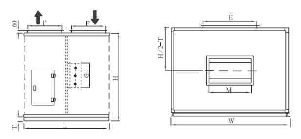
The airflow splitter section adjusts system airflow to meet design requirements. This section combines the exhaust air section with the fresh-air/secondary-return-air section. Unless otherwise specified, the unit is not supplied with airflow control dampers for the exhaust air or fresh-air/secondary-return-air sections. An airflow control damper and an access door are provided inside.
The exhaust air section can be used with a return fan as a full-return-air system during intermediate seasons, or to adjust system airflow and the fresh-air-to-return-air mixing ratio. The secondary return air section is used for secondary return-air mixing in systems with secondary return air, or to mix fresh air with return air.

Model Size | H | w | L | E | F | M | G | T |
ZK0102 | 500 | 720 | 1300 | 200 | 200 | _ | _ | 100 |
ZK0202 | 820 | 720 | 1300 | 320 | 200 | _ | _ | 100 |
ZK0203 | 820 | 1040 | 1300 | 400 | 320 | _ | _ | 100 |
ZK0303 | 1140 | 1040 | 1300 | 400 | 400 | _ | _ | 100 |
ZK0304 | 1140 | 1360 | 1300 | 630 | 400 | _ | _ | 100 |
ZK0404 | 1460 | 1360 | 1300 | 630 | 500 | _ | _ | 100 |
ZK0405 | 1460 | 1680 | 1300 | 1000 | 500 | 800 | 630 | 100 |
ZK0505 | 1780 | 1680 | 1300 | 1000 | 630 | 1000 | 630 | 100 |
ZK0506 | 1780 | 2000 | 1700 | 1600 | 630 | 1000 | 800 | 100 |
ZK0606 | 2100 | 2000 | 1700 | 1600 | 630 | 1000 | 1000 | 100 |
ZK0607 | 2160 | 2360 | 1800 | 1800 | 630 | 1000 | 1000 | 120 |
ZK0707 | 2480 | 2360 | 1800 | 2000 | 630 | 1200 | 1200 | 120 |
ZK0708 | 2480 | 2680 | 2100 | 2200 | 800 | 1200 | 1400 | 120 |
ZK0808 | 2800 | 2680 | 2100 | 2200 | 800 | 1400 | 1400 | 120 |
ZK0809 | 2800 | 3000 | 2100 | 2500 | 800 | 1400 | 1500 | 120 |
ZK0909 | 3120 | 3000 | 2500 | 2500 | 1000 | 1600 | 1600 | 120 |
ZK0910 | 3120 | 3320 | 2500 | 2500 | 1000 | 1600 | 1600 | 120 |
ZK1010 | 3440 | 3320 | 2500 | 2500 | 1000 | 1800 | 1800 | 120 |
ZK1011 | 3440 | 3640 | 2500 | 3000 | 1000 | 2000 | 2000 | 120 |
ZK1111 | 3760 | 3640 | 2500 | 3000 | 1000 | 2000 | 2000 | 120 |
ZK1113 | 3760 | 4280 | 2500 | 3500 | 1000 | 2200 | 2000 | 120 |
ZK1115 | 3760 | 4920 | 3000 | 3600 | 1200 | 2200 | 2000 | 120 |
ZK1117 | 3760 | 5560 | 3700 | 4000 | 1600 | 2500 | 2500 | 120 |
Energy Recovery Section
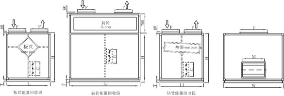
The energy recovery section transfers energy from the exhaust air to the fresh air through a heat exchanger. Energy recovery efficiency can exceed 70%, significantly reducing operating costs, saving energy, protecting the environment, and improving air quality. Unless otherwise specified, the unit is not supplied with airflow control dampers for exhaust air and fresh air. An airflow control damper is provided only inside the section. It can be used to adjust system airflow and the fresh-air-to-return-air mixing ratio, or for full-return-air/fresh-air systems during intermediate seasons.
Users can choose from three types of energy recovery sections: plate, rotary, and heat pipe. Plate and rotary types are available in two configurations: sensible heat recovery and total heat recovery. The heat pipe type is available only for sensible heat recovery.

Model Size | H | w | L1 | L2 | E | F | M | G | T |
ZK0102 | 500 | 720 | _ | _ | 200 | 200 | _ | _ | 100 |
ZK0202 | 820 | 720 | 1300 | 1300 | 320 | 200 | 400 | 320 | 100 |
ZK0203 | 820 | 1040 | 1300 | 1300 | 400 | 320 | 400 | 400 | 100 |
ZK0303 | 1140 | 1040 | 1300 | 1300 | 400 | 400 | 400 | 400 | 100 |
ZK0304 | 1140 | 1360 | 1300 | 1300 | 630 | 400 | 500 | 400 | 100 |
ZK0404 | 1460 | 1360 | 1300 | 1300 | 630 | 500 | 630 | 400 | 100 |
ZK0405 | 1460 | 1680 | 1500 | 1500 | 1000 | 500 | 630 | 500 | 100 |
ZK0505 | 1780 | 1680 | 1500 | 1500 | 1000 | 630 | 1000 | 500 | 100 |
ZK0506 | 1780 | 2000 | 1500 | 1500 | 1600 | 630 | 1250 | 630 | 100 |
ZK0606 | 2100 | 2000 | 1700 | 1700 | 1600 | 630 | 1250 | 630 | 100 |
ZK0607 | 2160 | 2360 | 1700 | 1800 | 1800 | 630 | 1250 | 800 | 120 |
ZK0707 | 2480 | 2360 | 1700 | 2100 | 2000 | 630 | 1250 | 800 | 120 |
ZK0708 | 2480 | 2680 | 2200 | 2200 | 2200 | 800 | 1250 | 1000 | 120 |
ZK0808 | 2800 | 2680 | 2300 | 2300 | 2200 | 800 | 1250 | 1000 | 120 |
ZK0809 | 2800 | 3000 | 2100 | 2500 | 2500 | 800 | 1600 | 1000 | 120 |
ZK0909 | 3120 | 3000 | 2500 | 2600 | 2500 | 1000 | 1600 | 1000 | 120 |
ZK0910 | 3120 | 3320 | 2500 | 2800 | 2500 | 1000 | 1600 | 1250 | 120 |
ZK1010 | 3440 | 3320 | 2500 | 3100 | 2500 | 1000 | 1800 | 1250 | 120 |
ZK1011 | 3440 | 3640 | 2500 | 3300 | 3000 | 1000 | 2000 | 1250 | 120 |
ZK1111 | 3760 | 3640 | 2500 | 3500 | 3000 | 1000 | 2520 | 1250 | 120 |
ZK1113 | 3760 | 4280 | 2500 | 3700 | 3500 | 1000 | 2500 | 1250 | 120 |
ZK1115 | 3760 | 4920 | 2900 | 4100 | 3600 | 1200 | 2500 | 1250 | 120 |
ZK1117 | 3760 | 5560 | 3700 | 5100 | 4000 | 1600 | 3000 | 1600 | 120 |
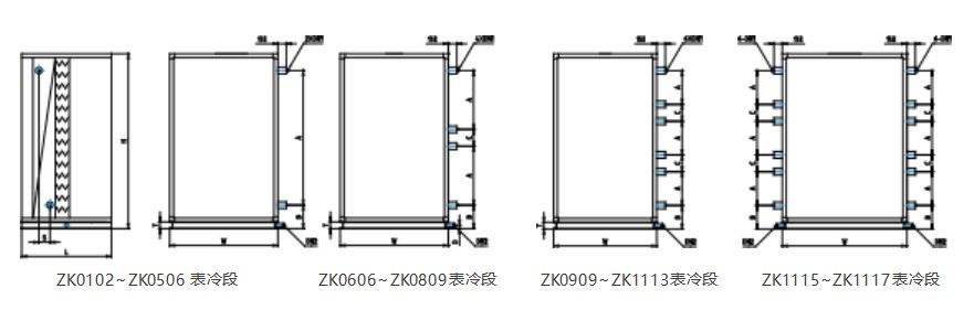
Cooling Coil (Heating) and Moisture Eliminator Section
The cooling coil and moisture eliminator section provides cooling, dehumidification, and droplet separation. It can also heat air using hot water below 65℃. A drain pan and condensate drain pipe are installed at the bottom. A moisture eliminator is required when the unit's face velocity is >2.5m/s.
To facilitate on-site installation and maintenance of the cooling coils, ZK20~ZK60 units use two cooling coils stacked vertically, while ZK70~ZK100 units use three coils stacked vertically and operating in parallel.

|
|
|
|
|
|
|
|
|
|
|
|
|
|
|
|
|
|
|
|
|
ZK0102 | 500 | 720 | 700 | 170 | 200 |
| 25 | 100 | 40 |
| 40 | 82.5 | 40 | 137.5 | 40 | 192.5 |
ZK0202 | 820 | 720 | 700 | 520 | 200 |
| 25 | 100 | 40 |
| 40 | 82.5 | 40 | 137.5 | 40 | 192.5 |
ZK0203 | 820 | 1040 | 700 | 520 | 200 |
| 25 | 100 | 40 |
| 40 | 82.5 | 40 | 137.5 | 50 | 192.5 |
ZK0303 | 1140 | 1040 | 700 | 830 | 200 |
| 32 | 100 | 40 |
| 40 | 82.5 | 40 | 137.5 | 50 | 192.5 |
ZK0304 | 1140 | 1360 | 700 | 830 | 200 |
| 32 | 100 | 40 |
| 50 | 82.5 | 50 | 137.5 | 65 | 192.5 |
ZK0404 | 1460 | 1360 | 700 | 1100 | 215 |
| 32 | 100 | 40 |
| 50 | 82.5 | 50 | 137.5 | 65 | 192.5 |
ZK0405 | 1460 | 1680 | 700 | 1100 | 215 |
| 32 | 100 | 50 |
| 50 | 82.5 | 65 | 137.5 | 65 | 192.5 |
ZK0505 | 1780 | 1680 | 700 | 1443 | 215 |
| 40 | 100 | 50 |
| 65 | 82.5 | 65 | 137.5 | 65 | 192.5 |
ZK0506 | 1780 | 2000 | 700 | 1443 | 215 |
| 40 | 100 | 50 |
| 65 | 82.5 | 65 | 137.5 | 65 | 192.5 |
|
|
|
|
|
|
|
|
|
|
|
|
|
|
|
|
|
|
|
|
|
|
ZK0606 | 2100 | 2000 | 700 | 810 | 215 | 105 | 40 | 100 | 50 | 66 | 65 | 82.5 | 80 | 137.5 | 80 | 192.5 |
ZK0607 | 2160 | 2360 | 700 | 843 | 250 | 105 | 40 | 120 | 50 | 66 | 65 | 99 | 80 | 165 | 80 | 231 |
ZK0707 | 2480 | 2360 | 700 | 991 | 250 | 105 | 40 | 120 | 50 | 66 | 65 | 99 | 80 | 165 | 80 | 231 |
ZK0708 | 2480 | 2680 | 800 | 978 | 253 | 108 | 50 | 120 | 50 | 66 | 80 | 99 | 80 | 165 | 80 | 231 |
ZK0808 | 2800 | 2680 | 800 | 1130 | 253 | 108 | 50 | 120 | 50 | 66 | 80 | 99 | 80 | 165 | 80 | 231 |
ZK0809 | 2800 | 3000 | 800 | 1130 | 253 | 108 | 50 | 120 | 50 | 66 | 80 | 99 | 80 | 165 | 80 | 231 |
|
|
|
|
|
|
|
|
|
|
|
|
|
|
|
|
|
|
|
|
|
ZK0909 | 3120 | 3000 | 800 | 829 | 253 | 105 | 50 | 120 | 50 | 66 | 65 | 99 | 80 |
| 80 |
|
ZK0910 | 3120 | 3320 | 800 | 829 | 253 | 105 | 50 | 120 | 65 | 80 | 65 | 99 | 80 |
| 80 |
|
ZK1010 | 3440 | 3320 | 800 | 902 | 253 | 105 | 50 | 120 | 65 | 80 | 80 | 99 | 80 |
| 80 |
|
ZK1011 | 3440 | 3640 | 800 | 902 | 253 | 105 | 50 | 120 | 65 | 80 | 80 | 99 | 80 |
| 100 |
|
ZK1111 | 3760 | 3640 | 800 | 1012 | 253 | 105 | 65 | 120 | 65 | 80 | 80 | 99 | 100 |
| 100 |
|
ZK1113 | 3760 | 4280 | 800 | 1012 | 253 | 105 | 65 | 120 | 80 | 99 | 100 | 130 | 100 |
| 100 |
|
ZK1115 | 3760 | 4920 | 800 | 1012 | 253 | 105 | 65 | 120 | 80 | 99 | 80 | 130 | 80 |
| 80 |
|
ZK1117 | 3760 | 5560 | 800 | 1012 | 253 | 105 | 65 | 120 | 80 | 99 | 80 | 130 | 80 |
| 80 |
|
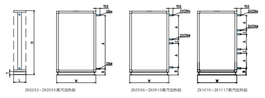
Steam Heating Section
The steam heating tubes in this section use a steel-aluminum composite extrusion structure, offering high heating efficiency, high internal pressure strength, an attractive appearance, corrosion resistance, resistance to microbial growth, and a long service life.

|
|
|
|
|
|
| α | β |
|
ZK0102 | 500 | 720 | 300 | 200 | 260 | _ | 32 | 25 | 100 |
ZK0202 | 820 | 720 | 300 | 320 | 260 | _ | 32 | 25 | 100 |
ZK0203 | 820 | 1040 | 300 | 320 | 260 | _ | 32 | 25 | 100 |
ZK0303 | 1140 | 1040 | 300 | 640 | 260 | _ | 32 | 25 | 100 |
ZK0304 | 1140 | 1360 | 300 | 640 | 260 | _ | 32 | 25 | 100 |
ZK0404 | 1460 | 1360 | 300 | 960 | 260 | _ | 50 | 40 | 100 |
ZK0405 | 1460 | 1680 | 300 | 960 | 260 | _ | 50 | 40 | 100 |
ZK0505 | 1780 | 1680 | 300 | 1410 | 260 | _ | 50 | 40 | 100 |
ZK0506 | 1780 | 2000 | 300 | 540 | 260 | 200 | 40 | 32 | 100 |
|
|
|
|
|
|
|
|
|
|
|
|
|
| α | β |
|
ZK0606 | 2100 | 2000 | 300 | 700 | 260 | 200 | 40 | 32 | 100 |
ZK0607 | 2160 | 2360 | 300 | 700 | 300 | 220 | 50 | 40 | 120 |
ZK0707 | 2480 | 2360 | 300 | 855 | 300 | 220 | 50 | 40 | 120 |
ZK0708 | 2480 | 2680 | 300 | 855 | 300 | 220 | 50 | 40 | 120 |
ZK0808 | 2800 | 2680 | 300 | 1015 | 300 | 220 | 50 | 40 | 120 |
ZK0809 | 2800 | 3000 | 300 | 1015 | 300 | 220 | 65 | 50 | 120 |
ZK0909 | 3120 | 3000 | 300 | 1175 | 300 | 220 | 65 | 50 | 120 |
ZK0910 | 3120 | 3320 | 300 | 1175 | 300 | 220 | 65 | 50 | 120 |
|
|
48
Wetted Media Humidification Section
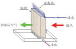
A wetted media humidifier humidifies air through the natural evaporation of water. Its medium is a paper-like material formed from polymeric inorganic materials through a series of sintering processes, with high water-absorption capacity. As dry air passes through the medium, water gradually evaporates and absorbs heat from the air, increasing its humidity. The humidifier can use ordinary domestic water or tap water and offers the following advantages:
Clean humidification___Wetted media humidification and cooling produces no “white dust.”
Short humidification distance___A short humidification distance saves space in the air handling unit.
High saturation efficiency___High saturation efficiency without oversaturation or condensation.
Safe and reliable___The media resists mold and bacteria and has a service life of 8~10 years.
Effective cooling___Direct evaporative cooling using a packed media method provides effective cooling in a compact size.

Technical Data Table for Evaporative Wetted Media Humidifiers
Wet Film Thickness (mm) | 50 | 100 | 150 | 200 | 300 |
Pressure Loss (Pa) | 30 | 50 | 75 | 83 | 90 |
Saturation Efficiency (%) | 30 | 55 | 70 | 80 | 93 |
Standard Humidification Capacity (kg/h per m²) | 23 | 44 | 56 | 84 | 72 |
Test Conditions | Inlet air conditions: dry-bulb temperature 40℃, relative humidity 15% RH, face velocity 2.5 m/s, and water temperature 20℃. |
Model Size | Reference Airflow (m³/h) | H | w | L | L 1 | Humidification Capacity under Fresh Air Conditions (kg/h) | Humidification Capacity under Return Air Conditions (kg/h) |
30% Efficiency | 55% Efficiency | 70% Efficiency | 80% Efficiency | 30% Efficiency | 55% Efficiency | 70% Efficiency | 80% Efficiency |
ZK0102 | 1000_1200 | 500 | 720 | 700 | 900 | 3 | 8 | 10 | 11 | 3 | 6 | 8 | 9 |
ZK0202 | 1500_2500 | 820 | 720 | 700 | 900 | 4 | 10 | 11 | 12 | 4 | 7 | 9 | 10 |
ZK0203 | 2500_4500 | 820 | 1040 | 700 | 900 | 9 | 16 | 23 | 26 | 8 | 15 | 9 | 22 |
ZK0303 | 4500_7500 | 1140 | 1040 | 700 | 900 | 14 | 26 | 33 | 34 | 11 | 21 | 27 | 31 |
ZK0304 | 7500_10000 | 1140 | 1360 | 700 | 900 | 20 | 36 | 45 | 52 | 15 | 29 | 37 | 42 |
ZK0404 | 10000_14000 | 1460 | 1360 | 700 | 900 | 23 | 44 | 56 | 64 | 19 | 36 | 46 | 52 |
ZK0405 | 14000_18000 | 1460 | 1680 | 700 | 900 | 35 | 67 | 86 | 98 | 29 | 55 | 70 | 80 |
ZK0505 | 18000_25000 | 1780 | 1680 | 700 | 900 | 40 | 75 | 94 | 107 | 32 | 60 | 77 | 88 |
ZK0506 | 25000_30000 | 1780 | 2000 | 700 | 900 | 52 | 100 | 126 | 140 | 42 | 81 | 103 | 119 |
ZK0606 | 28000_34000 | 2100 | 2000 | 700 | 900 | 60 | 114 | 145 | 166 | 49 | 93 | 119 | 136 |
ZK0607 | 30000_41000 | 2160 | 2360 | 700 | 900 | 62 | 116 | 152 | 175 | 50 | 98 | 125 | 143 |
ZK0707 | 38000_48000 | 2480 | 2360 | 700 | 900 | 67 | 128 | 163 | 187 | 55 | 105 | 134 | 153 |
ZK0708 | 45000_56000 | 2480 | 2680 | 800 | 1000 | 91 | 175 | 222 | 254 | 75 | 143 | 182 | 208 |
ZK0808 | 50000_65000 | 2800 | 2680 | 800 | 1000 | 97 | 185 | 237 | 271 | 80 | 153 | 194 | 222 |
ZK0809 | 60000_73000 | 2800 | 3000 | 800 | 1000 | 122 | 233 | 297 | 339 | 100 | 191 | 243 | 278 |
ZK0909 | 70000_81000 | 3120 | 3000 | 800 | 1000 | 135 | 245 | 320 | 356 | 110 | 217 | 275 | 310 |
ZK0910 | 75000_91000 | 3120 | 3320 | 800 | 1000 | 140 | 266 | 338 | 386 | 115 | 226 | 286 | 323 |
ZK1010 | 80000_100000 | 3440 | 3320 | 800 | 1000 | 154 | 295 | 375 | 429 | 126 | 241 | 307 | 351 |
ZK1011 | 90000_110000 | 3440 | 3640 | 800 | 1000 | 193 | 332 | 422 | 482 | 142 | 272 | 346 | 395 |
ZK1111 | 100000_132000 | 3760 | 3640 | 800 | 1000 | 196 | 375 | 477 | 545 | 160 | 307 | 391 | 446 |
Note: L is the length of the cooling coil + direct-drain humidification section; L1 is the length of the cooling coil + recirculating-water wetted media humidification section.
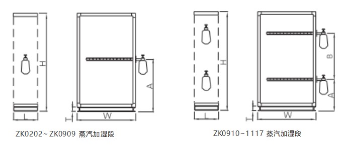
Dry Steam Humidification Section
The humidification section can use a steam humidifier to humidify the air. The humidification capacity is determined according to user requirements.
Made entirely of stainless steel, it offers high humidification efficiency, an attractive appearance, corrosion resistance, resistance to microbial growth, and a long service life.
The double-layer steam pipe is insulated to prevent water spray from the nozzles. A unique silencing mesh ensures that the dry steam humidifier operates without noise.

Note: Depending on the selected unit parameters, values A and B in the diagram or the number of humidifiers may be adjusted as appropriate.
51
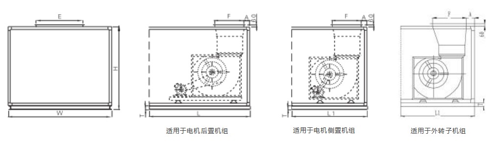
Top-Discharge Fan Section
The fan discharge section uses a high-efficiency centrifugal fan with double inlets. Vibration isolators are installed inside the section for stable and reliable operation. Unless otherwise specified, the unit is not supplied with an airflow control damper. An access door is provided.
When selecting the fan section, users should determine the fan's rated airflow and external static pressure based on the unit airflow, required residual pressure, and the unit's own resistance.
Air Handling Unit Model | H | W |
|
| A | E | F | T |
ZK0102 | 500 | 720 | _ | 700 | 50 | 200 | 200 | 100 |
ZK0202 | 820 | 720 | _ | 700 | 50 | 320 | 200 | 100 |
ZK0203 | 820 | 1040 | _ | 700 | 50 | 400 | 320 | 100 |
ZK0303 | 1140 | 1040 | _ | 800 | 50 | 400 | 400 | 100 |
ZK0304 | 1140 | 1360 | _ | 800 | 50 | 630 | 400 | 100 |
ZK0404 | 1460 | 1360 | 1500 | 1000 | 50 | 630 | 500 | 100 |
ZK0405 | 1460 | 1680 | 1600 | 1000 | 50 | 800 | 630 | 100 |
ZK0505 | 1780 | 1680 | 1900 | 1100 | 50 | 1000 | 630 | 100 |
ZK0506 | 1780 | 2000 | 1900 | 1300 | 50 | 1000 | 1000 | 100 |
ZK0606 | 2100 | 2000 | 1900 | 1300 | 50 | 1000 | 1000 | 100 |
ZK0607 | 2160 | 2360 | 2200 | 1400 | 70 | 1250 | 1000 | 120 |
ZK0707 | 2480 | 2360 | 2400 | 1600 | 70 | 1250 | 1000 | 120 |
ZK0708 | 2480 | 2680 | 2400 | 1600 | 70 | 1250 | 1250 | 120 |
ZK0808 | 2800 | 2680 | 2800 | 1800 | 70 | 1250 | 1250 | 120 |
ZK0809 | 2800 | 3000 | 2800 | 1800 | 70 | 1600 | 1250 | 120 |
ZK0909 | 3120 | 3000 | 3000 | 2000 | 70 | 1600 | 1600 | 120 |
ZK0910 | 3120 | 3320 | 3200 | 2200 | 70 | 1600 | 1600 | 120 |
ZK1010 | 3440 | 3320 | 3200 | 2200 | 70 | 1600 | 1600 | 120 |
ZK1011 | 3440 | 3640 | 3200 | 2200 | 70 | 1800 | 1600 | 120 |
ZK1111 | 3760 | 3640 | 3900 | 2300 | 70 | 1800 | 1600 | 120 |
ZK1113 | 3760 | 4280 | 4000 | 2600 | 70 | 2000 | 1800 | 120 |
ZK1115 | 3760 | 4920 | 4000 | 2800 | 70 | 2000 | 2000 | 120 |
ZK1117 | 3760 | 5560 | 3900 | 2800 | 70 | 2X1800 | 2X1800 | 120 |
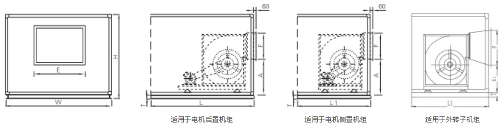
Horizontal-Discharge Fan Section
The fan discharge section uses a high-efficiency centrifugal fan with double inlets. Vibration isolators are installed inside the section for stable and reliable operation. Unless otherwise specified, the unit is not supplied with an airflow control damper. An access door is provided.
When selecting the fan section, users should determine the fan's rated airflow and external static pressure based on the unit airflow, required residual pressure, and the unit's own resistance. This section can also be used as a return fan section in conjunction with the airflow splitter section.

Air Handling Unit Model | H | W |
|
| E | F | T |
ZK0102 | 500 | 720 | _ | 700 | 200 | 200 | 100 |
ZK0202 | 820 | 720 | _ | 700 | 320 | 200 | 100 |
ZK0203 | 820 | 1040 | _ | 700 | 400 | 320 | 100 |
ZK0303 | 1140 | 1040 | _ | 800 | 400 | 400 | 100 |
ZK0304 | 1140 | 1360 | _ | 800 | 630 | 400 | 100 |
ZK0404 | 1460 | 1360 | 1500 | 1000 | 630 | 500 | 100 |
ZK0405 | 1460 | 1680 | 1500 | 1000 | 800 | 630 | 100 |
ZK0505 | 1780 | 1680 | 1700 | 1100 | 1000 | 630 | 100 |
ZK0506 | 1780 | 2000 | 1800 | 1400 | 1000 | 1000 | 100 |
ZK0606 | 2100 | 2000 | 1800 | 1400 | 1000 | 1000 | 100 |
ZK0607 | 2160 | 2360 | 2100 | 1400 | 1250 | 1000 | 120 |
ZK0707 | 2480 | 2360 | 2300 | 1700 | 1250 | 1000 | 120 |
ZK0708 | 2480 | 2680 | 2300 | 1700 | 1250 | 1250 | 120 |
ZK0808 | 2800 | 2680 | 2600 | 1700 | 1250 | 1250 | 120 |
ZK0809 | 2800 | 3000 | 2600 | 1700 | 1600 | 1250 | 120 |
ZK0909 | 3120 | 3000 | 2800 | 2100 | 1600 | 1600 | 120 |
ZK0910 | 3120 | 3320 | 3000 | 2300 | 1600 | 1600 | 120 |
ZK1010 | 3440 | 3320 | 3000 | 2300 | 1600 | 1600 | 120 |
ZK1011 | 3440 | 3640 | 3000 | 2300 | 1800 | 1600 | 120 |
ZK1111 | 3760 | 3640 | 3400 | 2100 | 1800 | 1600 | 120 |
ZK1113 | 3760 | 4280 | 3400 | 2300 | 2000 | 1800 | 120 |
ZK1115 | 3760 | 4920 | 3500 | 2300 | 2000 | 2000 | 120 |
ZK1117 | 3760 | 5560 | 3500 | 2300 | 2X1800 | 2X1800 | 120 |
|
|
|
|
|
|
|
|
Note: Dimensions A and A1 depend on the specific fan selected. Reference heights are based on the unit being centered.
Reference Weights of Air Handling Unit Functional Sections
Air Handling Unit Model | 0102 | 0202 | 0203 | 0303 | 0304 | 0404 | 0405 | 0505 | 0506 | 0606 | 0607 | 0707 |
Mixing Section | 55 | 60 | 70 | 75 | 80 | 90 | 100 | 120 | 150 | 170 | 190 | 210 |
Filter | Panel Pre-Filter Section | 20 | 25 | 35 | 40 | 45 | 50 | 60 | 80 | 90 | 100 | 115 | 140 |
Bag Medium-Efficiency Filter Section | 60 | 65 | 75 | 85 | 100 | 100 | 110 | 130 | 140 | 170 | 190 | 240 |
High-Efficiency Filter Section | 75 | 76 | 86 | 98 | 115 | 115 | 127 | 150 | 161 | 196 | 219 | 276 |
Airflow Diversion Section | 86 | 100 | 140 | 150 | 160 | 180 | 200 | 200 | 300 | 340 | 380 | 600 |
Rotary Wheel Energy Recovery Section | 120 | 120 | 180 | 200 | 225 | 290 | 320 | 410 | 470 | 690 | 870 | 1040 |
Cooling <Heating> Coil Droplet Eliminator Section | 4 Rows | 115 | 123 | 175 | 192 | 208 | 233 | 242 | 308 | 433 | 592 | 667 | 742 |
6 Rows | 143 | 165 | 210 | 230 | 250 | 280 | 290 | 370 | 520 | 710 | 800 | 890 |
8 Rows | 183 | 203 | 250 | 270 | 290 | 340 | 340 | 440 | 620 | 840 | 950 | 1060 |
Steam Heating Section | 1 Row | 76 | 86 | 105 | 110 | 120 | 140 | 150 | 190 | 230 | 260 | 300 | 330 |
2 Rows | 96 | 102 | 120 | 130 | 135 | 160 | 180 | 230 | 280 | 310 | 360 | 400 |
3 Rows | 112 | 113 | 132 | 143 | 149 | 176 | 198 | 253 | 308 | 341 | 396 | 440 |
Steam Humidification Section | 60 | 65 | 81 | 86 | 92 | 104 | 115 | 138 | 173 | 196 | 219 | 345 |
Intermediate Section | 46 | 50 | 70 | 75 | 80 | 90 | 100 | 125 | 150 | 170 | 200 | 215 |
Airflow Equalizing Section | 59 | 68 | 77 | 83 | 88 | 99 | 110 | 132 | 165 | 187 | 209 | 330 |
Fan Section | 230 | 250 | 300 | 300 | 300 | 350 | 400 | 500 | 650 | 700 | 800 | 900 |
Supply Air Section | 54 | 60 | 70 | 75 | 80 | 90 | 100 | 120 | 150 | 470 | 190 | 300 |
Sound Attenuation Section | 112 | 120 | 150 | 170 | 200 | 200 | 255 | 300 | 320 | 350 | 400 | 450 |
Air Handling Unit Model | 0708 | 0808 | 0809 | 0909 | 0910 | 1010 | 1011 | 1111 | 1113 | 1115 | 1117 |
Mixing Section | 260 | 280 | 310 | 360 | 440 | 520 | 560 | 600 | 652 | 690 | 720 |
Filter | Panel Pre-Filter Section | 170 | 190 | 205 | 230 | 280 | 340 | 360 | 390 | 425 | 450 | 475 |
Bag Medium-Efficiency Filter Section | 300 | 330 | 360 | 410 | 500 | 590 | 640 | 690 | 730 | 780 | 820 |
High-Efficiency Filter Section | 345 | 380 | 414 | 472 | 575 | 679 | 736 | 794 | 824 | 870 | 920 |
Airflow Diversion Section | 750 | 820 | 900 | 1040 | 1260 | 1480 | 1610 | 1740 | 1850 | 1950 | 2050 |
Rotary Wheel Energy Recovery Section | 1140 | 1250 | 1290 | 1440 | 1550 | 1660 | 1770 | 2510 | 2680 | 2760 | 2960 |
Cooling <Heating> Coil Droplet Eliminator Section | 4 Rows | 900 | 967 | 1025 | 1167 | 1333 | 1500 | 1633 | 1750 | 1860 | 1970 | 2040 |
6 Rows | 1080 | 1160 | 1230 | 1400 | 1600 | 1800 | 1960 | 2100 | 2230 | 2350 | 2430 |
8 Rows | 1280 | 1380 | 1470 | 1670 | 1900 | 2140 | 2330 | 2510 | 2750 | 2860 | 2900 |
Steam Heating Section | 1 Row | 410 | 450 | 490 | 560 | 690 | 810 | 780 | 750 | 850 | 962 | 1020 |
2 Rows | 500 | 560 | 600 | 690 | 760 | 840 | 880 | 930 | 1020 | 1130 | 1210 |
3 Rows | 550 | 616 | 660 | 759 | 836 | 924 | 968 | 1023 | 1130 | 1250 | 1350 |
Steam Humidification Section | 431 | 472 | 518 | 598 | 725 | 851 | 926 | 1001 | 1500 | 1650 | 1730 |
Intermediate Section | 265 | 300 | 320 | 370 | 450 | 530 | 570 | 610 | 750 | 810 | 860 |
Airflow Equalizing Section | 413 | 451 | 495 | 572 | 693 | 814 | 886 | 957 | 1020 | 1150 | 1260 |
Fan Section | 950 | 1150 | 1270 | 1400 | 1490 | 2050 | 3350 | 3400 | 3600 | 3700 | 3820 |
Supply Air Section | 375 | 410 | 450 | 520 | 630 | 740 | 805 | 870 | 980 | 1130 | 1240 |
Sound Attenuation Section | 560 | 610 | 670 | 770 | 940 | 1110 | 1200 | 1300 | 1400 | 1480 | 1560 |
Note: Fan section weight is based on the weight of the largest motor matched to the same overall dimensions. Fan weight depends on airflow and total pressure.