


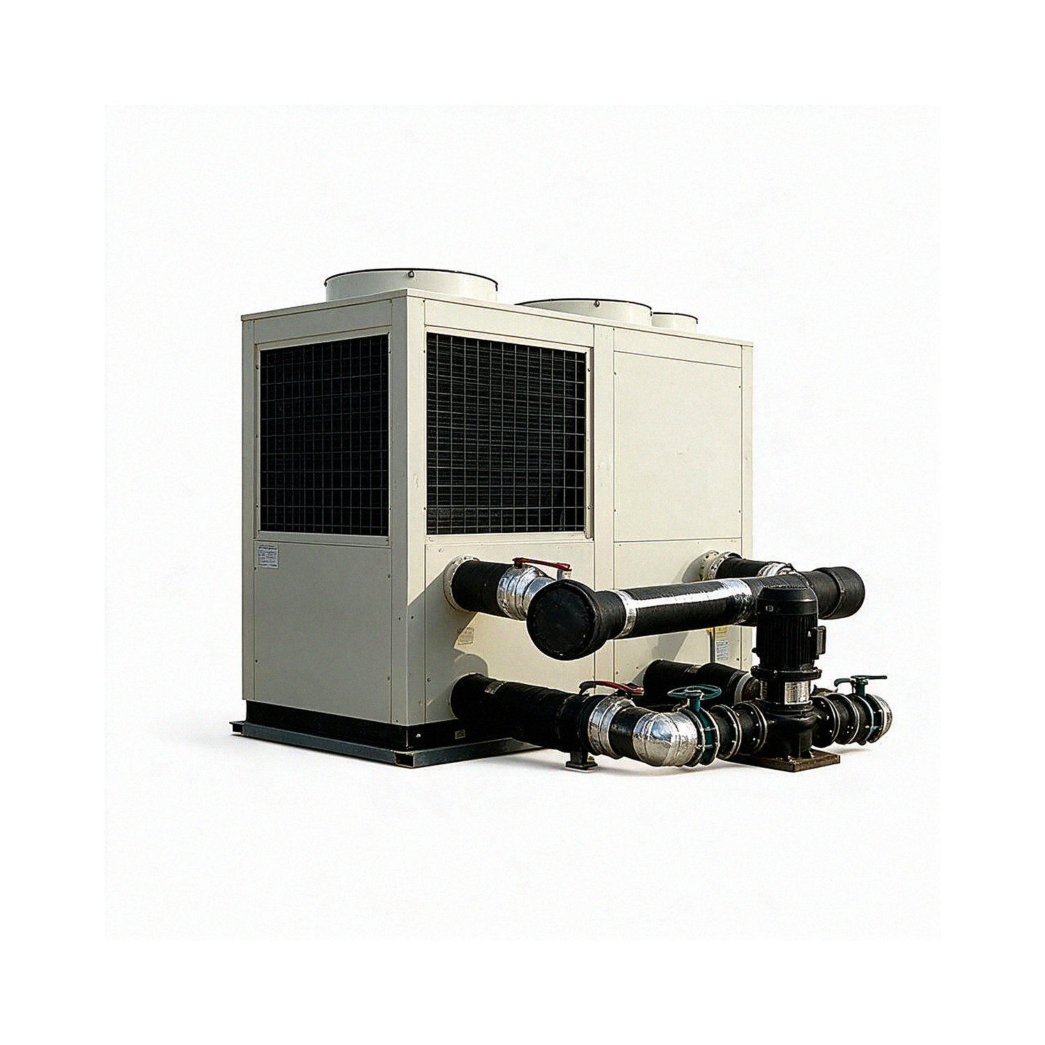
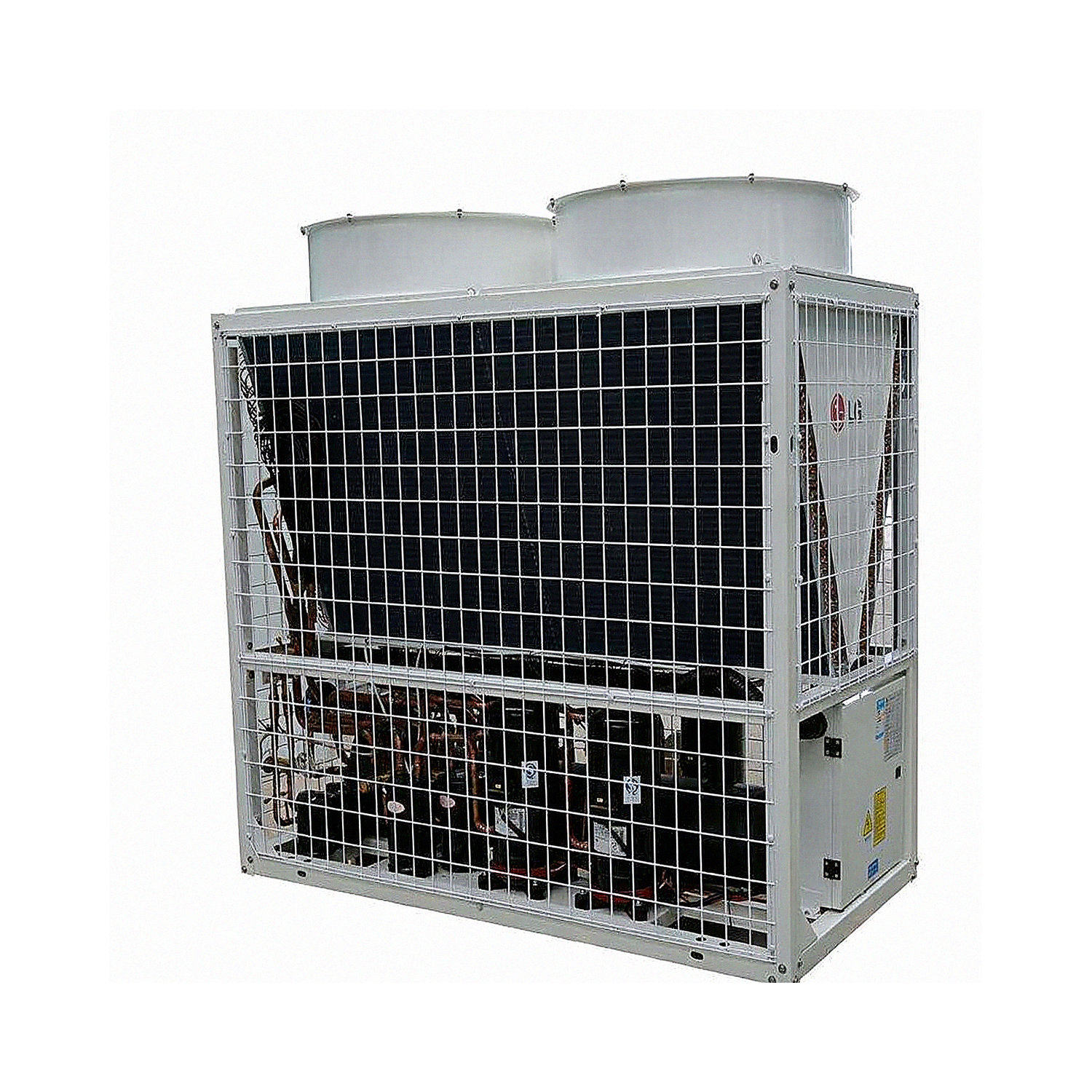
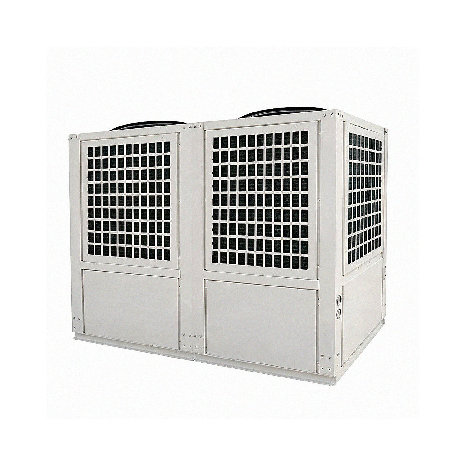
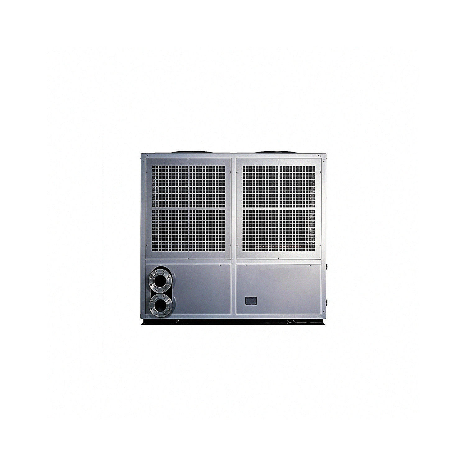
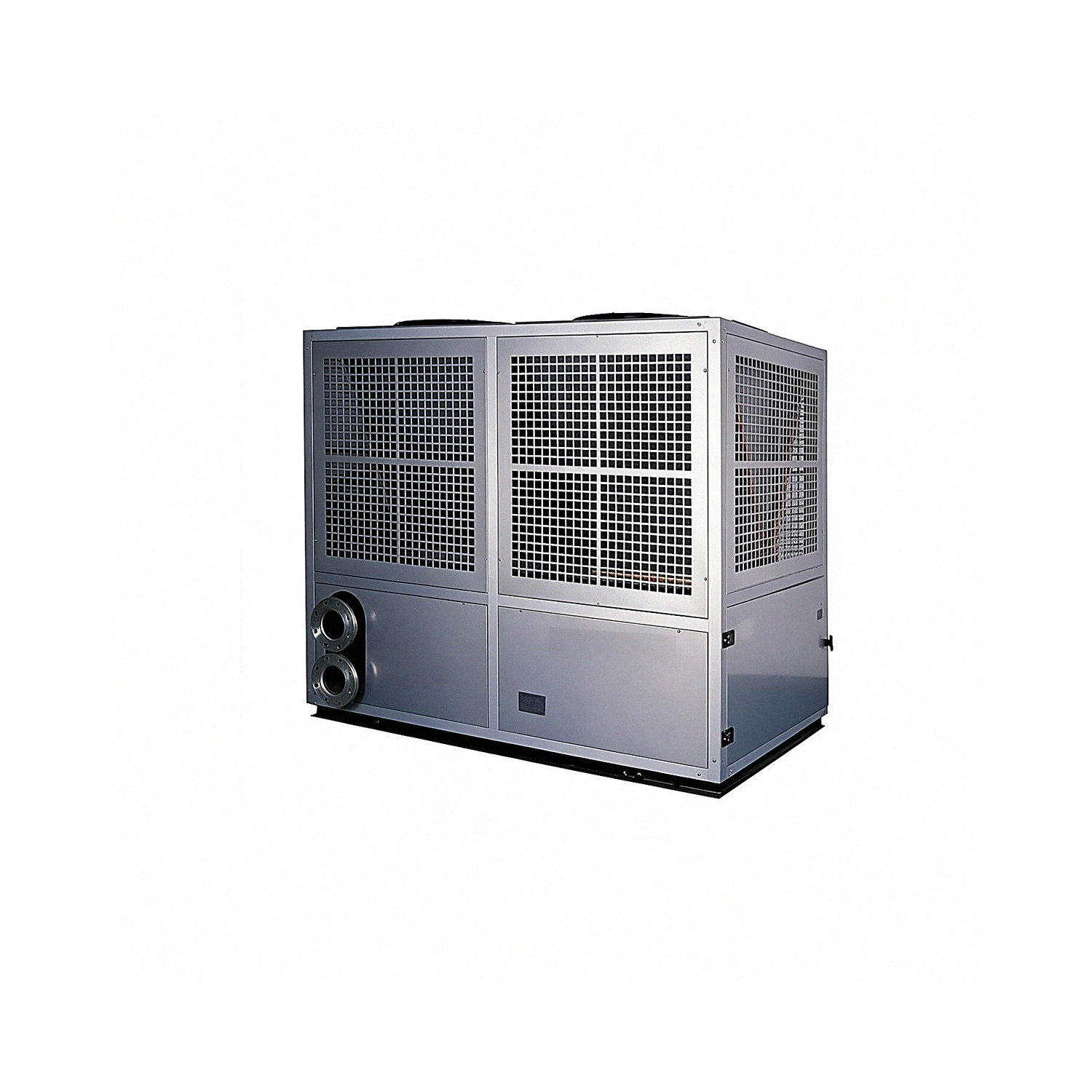
Product Overview
The air-cooled screw chiller/heater uses air as its cooling or heat source and water as the heat-transfer medium. Combining cooling and heating in one unit, it can operate year-round and offers environmental friendliness, energy efficiency, comfort, and reliable performance.
Combining the best in design, manufacturing, and application, the air-cooled screw chiller/heater features a range of core technologies, including high-capacity heating at low temperatures, multiple freeze-protection measures, intelligent defrost, and intelligent control. It delivers high operating reliability across a wide operating range and is available in a variety of models. It is widely used in public facilities such as hotels, shopping malls, office buildings, exhibition centers, airports, and sports arenas, and meets the diverse air-conditioning requirements of industrial processes in the electronics, pharmaceutical, biotechnology, textile, chemical, metallurgical, power, and machinery industries.
Product Advantages
1. No dedicated plant room required, reducing initial investment
Compared with boilers and water-cooled chillers/heaters, the unit is installed outdoors and requires no dedicated plant room, cooling tower, well, or buried piping, reducing the user's initial investment.
2. High efficiency and energy savings, environmentally friendly and safe
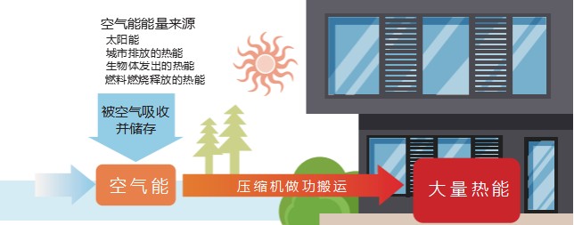
By absorbing a large amount of free energy from the air, the air-cooled screw chiller/heater delivers high energy efficiency and can save 75% of electricity compared with electric heating.
It uses environmentally friendly R407C and R134a refrigerants, with an ozone depletion potential (ODP) of 0. Compared with conventional boiler equipment, it involves no combustion or exhaust emissions and presents no flammable or explosive safety hazards.
3. Wide operating range and broad applicability
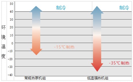
A variety of models are available to meet different requirements. The unit can operate reliably in heating mode at ambient temperatures as low as -35℃ and in cooling mode at ambient temperatures from -30℃ to 48℃.
4. Intelligent control; no on-site operator required
After one-touch startup, the intelligent control system monitors the unit's operating status in real time and automatically adjusts its capacity according to the actual load. No dedicated operator is required, reducing labor costs.
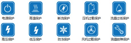
5. Multiple protection functions ensure reliable operation
The unit features multiple protection functions and automatically issues an alarm in real time if a fault occurs.
High Efficiency and Energy Savings
1. Precise refrigerant flow control with an electronic expansion valve
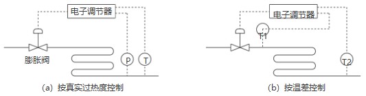
The electronic expansion valve opening is precisely controlled based on suction superheat, effectively resolving the lag and inaccuracy of temperature measurements in conventional temperature-difference control. This provides faster response and greater precision, optimizing and improving cooling, heating, and defrost performance across the operating range.
2. Intelligent defrost technology reduces heating capacity degradation
1) Multiple frost-suppression measures reduce frost formation under the same operating conditions.
● High-air-velocity frost suppression
High-volume fans enhance heat exchange on the evaporator side, raise the evaporation temperature, and reduce frost formation.
● Low-resistance fin frost suppression
The number of tube passes in the finned heat exchanger is matched to the airflow velocity field. Reducing the number of tube rows lowers resistance and improves heat transfer, effectively suppressing frost formation.
● The fin structure is comprehensively optimized to increase heat-transfer area, raise the evaporation temperature, and reduce frost formation.
2) Precise frost detection and fast defrost prevent misjudgments and unnecessary defrost cycles from affecting heat-transfer performance.
For precise detection, the unit uses high-accuracy pressure sensors to determine defrost conditions. Compared with conventional localized temperature detection, this method has a smaller margin of error and greater accuracy.
Triple-stage intelligent defrost control: the first stage determines defrost conditions based on the low-pressure reading; the second dynamically detects the temperature difference between the coil inlet and outlet to account for humidity differences across regions; if a pressure sensor fails, the third stage automatically switches the defrost determination to the second-stage logic, improving overall reliability.
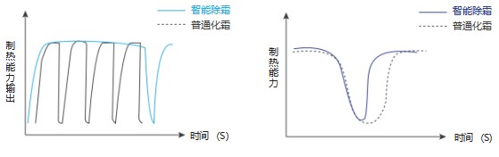
Combining precise frost detection with triple-stage intelligent defrost control, the system defrosts when frost is present and heats when it is not, reducing heating capacity degradation and improving heat-transfer performance.
3. Multiple intelligent freeze-protection measures for the water system
In winter heating mode, the unit provides multiple intelligent freeze-protection functions to prevent incidents such as frozen and burst water pipes and related equipment, as well as water leaks.
● When the leaving-water temperature falls below 6℃, the water pump runs until the ambient temperature rises above 6℃ and the protection is cleared;
● When the leaving-water temperature falls below 4℃, auxiliary electric heating is activated until the leaving-water temperature rises above 8℃ and the protection is cleared;
● When the leaving-water temperature falls below 2℃, the unit starts and runs until the leaving-water temperature rises above 15℃ and the protection is cleared;

4. Intelligent control technology
The unit uses an advanced, highly integrated single-chip microcomputer and a high-resolution, large-screen LCD to provide convenient service and easy maintenance. It supports multiple control functions, including local control, centralized control, and cloud-based intelligent remote monitoring.

Local control: LCD controller for simple, convenient operation.
Centralized control: An R485 interface is available as an option for monitoring unit operation through a centralized control system. Cloud-based intelligent remote services provide comprehensive system services throughout the product life cycle.
Key Components
Compressor
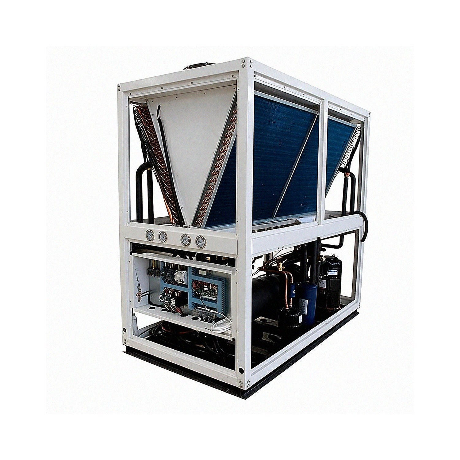
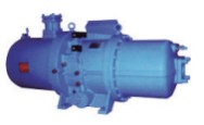
The unit uses a high-efficiency screw compressor from a well-known brand. R22, R407C, and R134a refrigerants are available. The compressor has a built-in high-efficiency oil separator, combining the separator and compressor into one unit to minimize the compressor's footprint and simplify the refrigerant circuit. An external oil-separation device can be added for special operating conditions.
High-Efficiency Air-Side Heat Exchanger
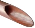
The unit's air-side heat exchanger features a distinctive V-shaped or inverted M-shaped structure that suits the airflow distribution characteristics while providing ample space for maintenance and servicing. The heat-exchange tubes are made of high-efficiency internally threaded copper, increasing the heat-transfer area and enhancing refrigerant turbulence for improved heat-transfer performance.
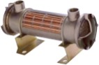
High-Efficiency Shell-and-Tube Heat Exchanger
The water-side heat exchanger is a high-efficiency shell-and-tube type protected by proprietary intellectual property (patent numbers: ZL 2017 2 1146129. 9、ZL 2015 2 1121635. 3、ZL 2015 2 1121636. 8、ZL 2017 2 0802667. 2). It delivers high heat-transfer efficiency, can be disassembled and cleaned, and is easy to maintain. It offers better freeze resistance than plate heat exchangers.
Expansion Valve
The electronic expansion valve control system offers control resolution of up to 6386 steps. Working with the electronic control system and using suction superheat and saturation pressure, it precisely controls refrigerant flow, keeping the unit at its optimal operating state and enabling it to deliver maximum capacity.

High-Efficiency, Low-Noise Fan
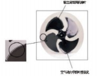
The fan blades' specially curved profile reduces noise.
The fan's optimized blade profile effectively eliminates noise peaks in the low-frequency range (125-250Hz). Suppressing the distribution of peak noise energy in this range delivers better acoustic performance, with noise energy more evenly distributed across the frequency spectrum. The advanced blade design also effectively suppresses boundary-layer separation and the resulting vortex zones as air flows over the rotating impeller, reducing blade noise.
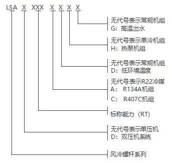
Air-Cooled Screw Chiller/Heater Models
Operating Range of Air-Cooled Screw Chillers/Heaters
● Large-diameter heat-exchange tubes reduce refrigerant flow resistance during low-temperature operation, increase evaporation pressure, and suppress frost formation;
● Wide fin spacing reduces airflow resistance during low-temperature operation, increases evaporation pressure, and suppresses frost formation;
● Independent control of fin circuits provides precise control and more thorough defrosting;
● A combination of innovative technologies, a distributed defrost system, and a piston-type four-way reversing valve effectively prevents issues found in conventional air-source heat pumps, including liquid refrigerant carryover into the suction line, incomplete defrosting, and four-way valve seizure.
Air-Cooled Screw Chiller/Heater Specification Table
07
Note: Standard cooling conditions: ambient temperature 35℃DB / leaving chilled-water temperature 7℃.
Standard heating conditions: ambient temperature 7℃DB / 6℃WB; leaving hot-water temperature 45℃. The parameters above are for reference only. Actual product specifications prevail.
Air-Cooled Screw Chiller/Heater Specification Table
Note: Rated cooling conditions: ambient temperature 35℃DB; leaving chilled-water temperature 7℃.
Rated heating conditions: ambient temperature 7℃DB / 6℃WB; leaving hot-water temperature 45℃. The parameters above are for reference only. Actual product specifications prevail.
Operating Range of Ultra-Low-Temperature, High-Heat Air-Cooled Screw Units
● Combines single-unit, two-stage compression technology with powerful vapor-injection enthalpy enhancement;
● Operates reliably at ambient temperatures as low as -35℃ and produces hot water up to 70℃; at -35℃, it can maintain a leaving-water temperature of 60℃;
● Environmentally friendly, internationally recognized R134a refrigerant is available as an option. It operates efficiently at low ambient temperatures and, at -12 ℃, delivers 180% higher energy efficiency than gas-fired and electric boilers. It is mainly used in heating energy stations in Northeast and Northwest China, high-temperature industrial processes, and other applications.
Ultra-Low-Temperature, High-Heat Air-Cooled Screw Unit Specification Table
1. Rated cooling conditions: ambient temperature 35℃, leaving chilled-water temperature 7℃;
2. Rated heating conditions: ambient temperature -12℃/-13.5°C, leaving hot-water temperature 41℃:
3. Complies with national standard GB/T25127:
4. Specifications and performance parameters may change as the product is improved without prior notice.
Cooling Capacity Correction Factor Table for Ultra-Low-Temperature, High-Heat Air-Cooled Screw Units
Heating Capacity Correction Factor Table for Ultra-Low-Temperature, High-Heat Air-Cooled Screw Units
Ultra-Low-Temperature, High-Heat Air-Cooled Screw Unit Specification Table
Note:
1. Rated heating conditions: ambient temperature -12℃/-13.5°C, leaving hot-water temperature 41℃;
2. Complies with national standard GB/T25127;
3. Specifications and performance parameters may change as the product is improved without prior notice.
Heating Capacity Correction Factor Table for Ultra-Low-Temperature, High-Heat Air-Cooled Screw Units
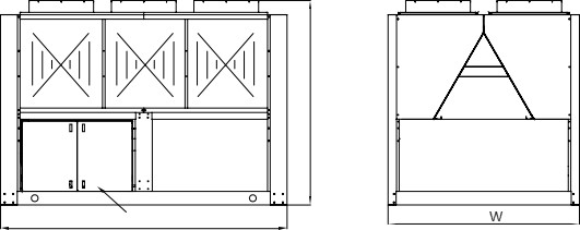
Air-cooled screw chiller/heater — single-compressor unit outline drawing
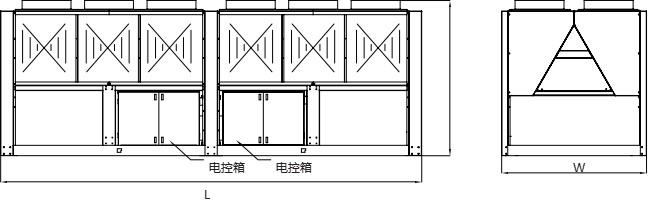
Air-cooled screw chiller/heater — dual-compressor unit outline drawing
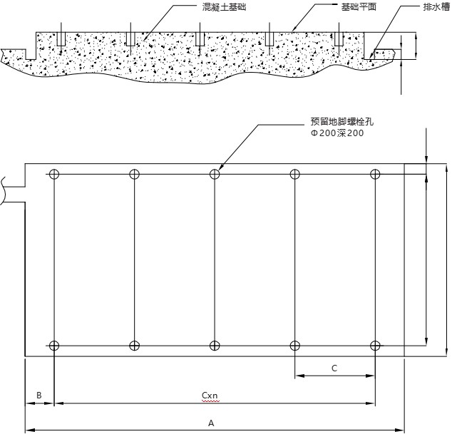
Note:
1. The installation foundation should be designed by qualified personnel based on site conditions;
2. The foundation must be made of concrete or steel, have sufficient strength to support the unit's operating weight, and have a level top surface with a drainage channel provided;
3. Install rubber vibration-isolation pads between the unit and the foundation; use vibration isolators for larger models;
4. Secure the unit with M16 anchor bolts;
5. Leave at least 1 . 5m of clearance around the unit to ensure airflow and allow equipment maintenance;
6. Leave at least 2.0-2.5m of clearance above the unit to ensure unobstructed airflow from the outlet.
Frequently Asked Questions
Please provide the model, airflow, total/static pressure, installation orientation, air inlet and outlet configuration, material, insulation, motor voltage/frequency, control method, filter module, smoke control and fire protection requirements, quantity, and packaging requirements. Performance, dimensions, and certification information are subject to the confirmed product and order documents.