


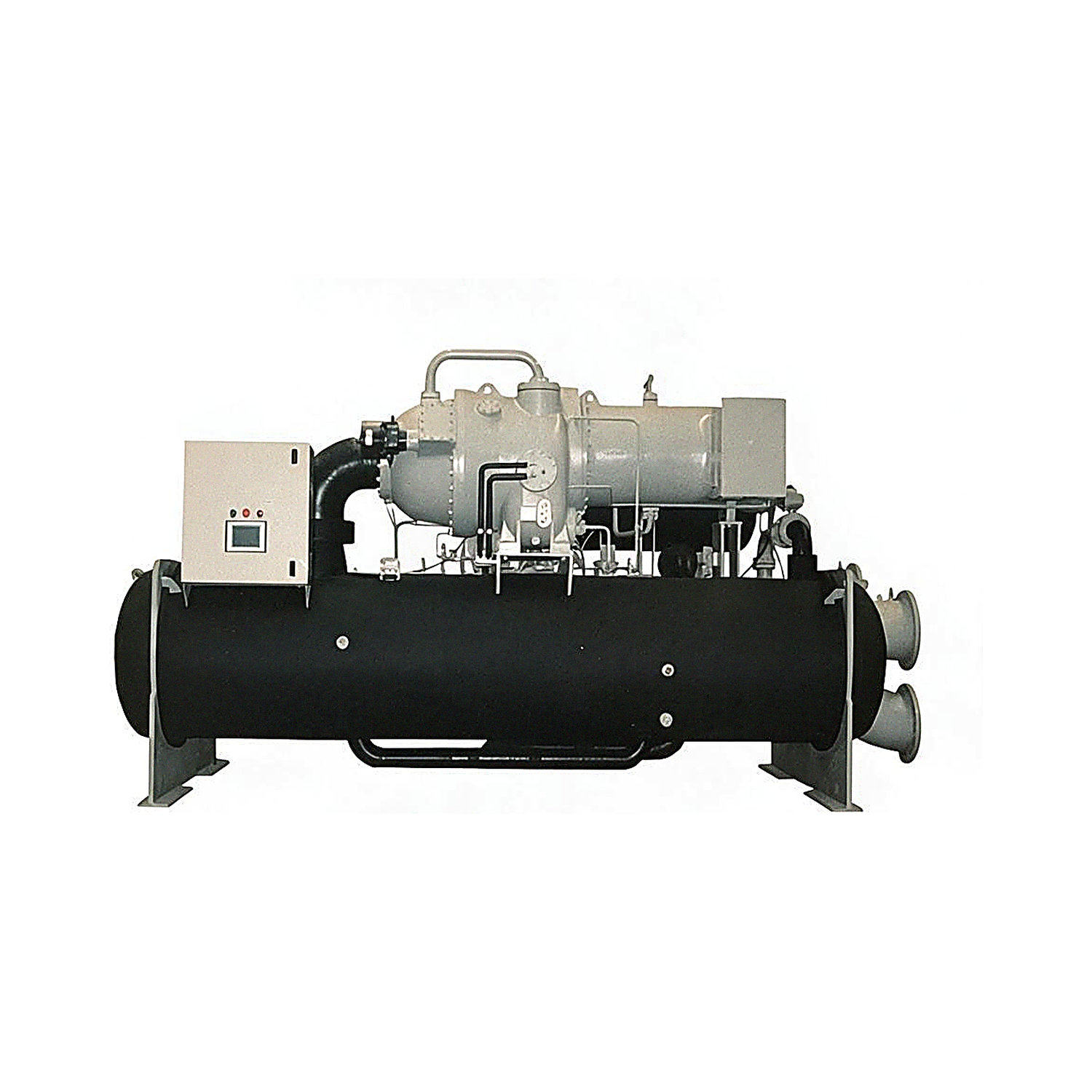
Product Overview
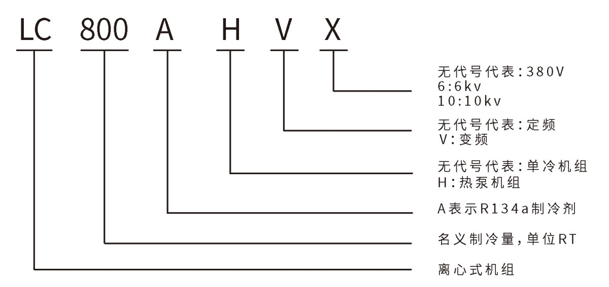
1. Centrifugal Chiller Model Naming Rules
Design, Inspection, and Manufacturing Standards
1. GB/T 18430.1 “Water-chilling (heat pump) packages using the vapor compression cycle—Part 1: Water-chilling (heat pump) packages for industrial or commercial and similar applications”
2. GB/T10870 “Methods of performance test for water-chilling (heat pump) packages using the vapor compression cycle”
3. NB/T 47012 “Pressure vessels for refrigeration equipment”
4. GB 25131 “Water-chilling (heat pump) packages using the vapor compression cycle—Safety requirements”
Product Applications
Widely used in large comfort air-conditioning systems in public facilities such as hotels, shopping malls, office buildings, exhibition centers, airports, and sports stadiums. They also meet the varying requirements of process air-conditioning systems in industries such as electronics, pharmaceuticals, biotechnology, textiles, chemicals, metallurgy, power generation, and machinery.
2. Layout of Main Product Components

(1) The compressor is a two-stage centrifugal type from a well-known imported brand.
Three-phase, two-pole squirrel-cage induction motor.
Y-△ starting, direct starting, or soft starting.
High-efficiency two-stage compression and economizer design.
Protection rating: IP54.
High-strength, enclosed aluminum impeller.
The high-speed shaft is made of high-strength alloy.
Under normal operating conditions, bearing life is up to 50,000 hours.
Highest efficiency in the HFC-134a centrifugal compressor market.

(2) The evaporator is a flooded or falling-film type.
Design pressure on the refrigerant side: 0.9 MPa.
High-efficiency heat-transfer tubes with external fins and internal threads are mechanically expanded and secured to the tube sheets.
The standard configuration is rated at 1.0 MPa, with 2–3 water passes on the water side. The water-side test pressure is 1.25 times the maximum working pressure.
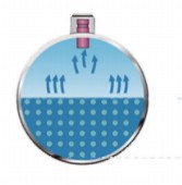

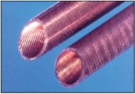
(3) The design pressure on the condenser refrigerant side is 1.3 MPa.
High-efficiency heat-transfer tubes with external fins and internal threads are mechanically expanded and secured to the tube sheets. The water-side test pressure is 1.25 times the maximum working pressure.

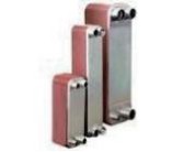
(4) The high-efficiency economizer has a carbon-steel shell. Its internal design prevents liquid refrigerant from entering the compressor. Intermediate refrigerant vapor injection into the compressor increases unit efficiency.
(5) The oil cooler is a high-efficiency plate heat exchanger. Oil temperature is controlled to cool the compressor lubricating oil.
3. Advanced Control System
(1) Color display for simpler touchscreen operation
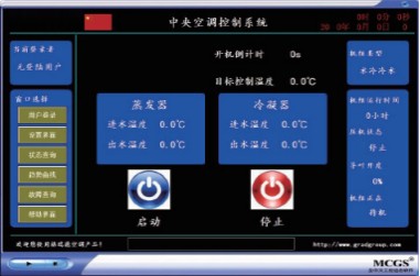
The touchscreen display and control center is an advanced microprocessor-based control system that provides users with a convenient, efficient, and visual operating interface. It also features real-time monitoring, data logging, and safety protection. The control center has an 8-inch color display. Users can tap the on-screen buttons to perform the corresponding functions, with clear, easy-to-read screens.
(2) More precise control and more stable output
The unit control system not only adjusts the load according to chilled-water conditions, but also predicts changes in air-conditioning load based on the rate of change in chilled-water inlet temperature. This enables faster load adjustment and more stable leaving-water temperature, avoids frequent load fluctuations, and extends compressor life.
(3) Unit protection functions
The unit has multiple protective measures, including power supply protection, compressor overheat and overload protection, system high- and low-pressure protection, and compressor oil sump temperature protection.
Freeze protection: Protects the system from heat exchanger damage caused by water system faults.
Oil/refrigerant heaters: The oil must be heated to above 40℃ before startup to ensure optimal lubrication. In cold regions, the refrigerant heater should be switched on before startup to prevent liquid compression in the compressor after startup.
Oil temperature protection: Alarm and protection thresholds are set for both excessively high and low oil temperatures to ensure proper compressor lubrication.
Sight glasses: Sight glasses are installed on the oil return line and the evaporator, condenser, and flash tank shells to observe the actual liquid/oil levels.
Emergency stop switch: Allows the unit to be stopped manually in an emergency.
Oil eductor: An eductor pump returns oil to ensure that oil in the system flows back to the compressor oil sump.
(4) Multiple anti-surge functions
The unit features advanced multiple anti-surge functions. By combining prevention, control, and alarms, it keeps the unit operating safely within its operating range while meeting the customer’s cooling capacity requirements.
Prevention: The unit automatically adjusts its load when its operating conditions approach the surge curve, based on precise calculations of the curve.
Control: Surge is promptly controlled when detected, effectively preventing it from occurring.
Alarm: If surge occurs during operation, an alarm message appears on the display to alert the customer, and the unit stops.
Interlock function: Control points are provided for the cooling tower fan, cooling water pump, and air-conditioning water pump.
Output points for remote start, alarm, and operating signals are provided for convenient remote operation.
The controller has an RS485 interface and supports the standard Modbus-RTU communication protocol, making it easy to integrate unit control into a building automation system.
(5) Display interface
When power is supplied to the centrifugal water-cooled chiller, the main screen appears after 10 seconds and displays unit operating parameters, including evaporator leaving-water temperature, evaporator entering-water temperature, condenser leaving-water temperature, condenser entering-water temperature, unit operating time, compressor status, inlet guide vane position, unit status, and target control temperature.
From the main screen, users can access other screens, such as “System Status,” “Compressor Status,” and “Analog Status,” to view the unit’s current operating status.
4. Unit Features
(1) The unit uses a two-stage centrifugal compressor for a high coefficient of performance.
Three-phase, two-pole squirrel-cage induction motor.
Y-△ starting, direct starting, or soft starting.
High-efficiency two-stage compression and economizer design.
Protection rating: IP54.
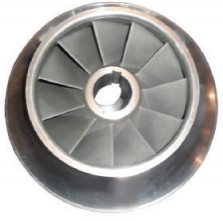
High-strength, enclosed aluminum impeller. An enclosed impeller is more efficient than an open impeller.
(2) Optional unit power supply voltages: 380V/6000V/10000V.
Selecting a higher voltage can reduce initial investment;
Low-speed operation at partial load reduces noise.
No transformer installation required; cable costs are reduced.
Electrical equipment installation costs and plant-room investment are reduced.
(3) The unit uses Siemens microcomputer-based intelligent control.
Simple operation, comprehensive protection, Chinese-language interface, and real-time monitoring, with clear display of operating data for convenient operation. The wide capacity control range enables stepless capacity adjustment from 10~100%. Comprehensive protection functions include power supply, high-pressure, low-pressure, and oil temperature protection, ensuring more reliable unit operation.
The unit features advanced multiple anti-surge functions. By combining prevention, control, and alarms, it meets customer cooling capacity requirements while keeping the unit within its safe operating range.
The display provides clear status information on switches, analog signals, inputs, alarms, and faults.
(4) Multiple unit throttling control options.
Depending on operating conditions and application requirements, users can choose from three throttling options: orifice plate, orifice plate in parallel with a solenoid valve, or orifice plate in parallel with an electric control valve.
Orifice plate and electric control valve in parallel provides the most precise throttling control, but at a higher cost, and is available as an option.
Each set of orifice plates is custom designed to match the centrifugal chiller and unit performance, providing an optimal match.
Since orifice plates have no moving parts, they are inherently more reliable than mechanically driven throttling valves.
(5) Independent oil return system.
The oil pump is built into the compressor. The independent oil return and oil cooling systems provide more reliable compressor lubrication.
The unit uses an eductor pump for oil return, powered by high-pressure gas to return oil from the low-pressure side.
(6) The unit uses environmentally friendly R134a refrigerant.
R134a is an HFC refrigerant recognized internationally as environmentally friendly.
(7) Compact design, small footprint, and low noise.
(8) The unit uses digital control technology to enable internet-based energy monitoring and remote operation. Optional remote intelligent services provide powerful functions, including remote data monitoring, rapid handling of unit faults, SMS alerts, and unit operating data storage.
(9) Centrifugal chiller equipped with VSD variable-frequency drive.
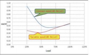
Greater energy savings at partial load
For projects with the same capacity, variable-frequency centrifugal chillers offer significant energy savings, reducing annual operating costs by approximately 30%.
Greater energy savings at low cooling-water temperatures
With a variable-frequency drive, compressor speed can be adjusted to accommodate changes in condensing temperature, maximizing the energy-saving benefits of low cooling-water temperatures.
More reliable operation
Coordinated capacity adjustment through compressor variable-frequency speed control and inlet guide vane control makes unit adjustment smoother and operation more stable and reliable.
Reduced impact on the power grid
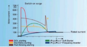
Since a variable-frequency centrifugal chiller starts at a very low speed, startup is smooth. Its starting current generally does not exceed 100% of the unit’s full-load amperage (FLA). This greatly reduces current surges, lowers investment in electrical equipment, and extends equipment service life.
Low-speed operation at partial load reduces noise
In theory, centrifugal water chillers using variable-frequency drive technology are approximately 8dB quieter than fixed-speed centrifugal chillers. Lower motor speed also extends the service life of unit components.
Because the variable-frequency cabinet of our variable-frequency units includes a DC reactor, the input-side power factor is maintained at no less than 0.95, significantly higher than the 0.8-0.9 of ordinary motors, reducing power supply investment costs.
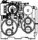
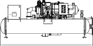
5. Product Outline Drawing
Centrifugal Water Chiller Technical Parameters
Notes:
1. Nominal conditions: Chilled-water inlet/outlet temperatures are --/7℃; cooling-water inlet/outlet temperatures are 30℃/--.
2. The evaporator fouling factor is 0.018㎡℃/kW, and the condenser fouling factor is 0.044㎡℃/kW.
3. The standard unit has a water-side pressure rating of 1 . 0MPa; options of 1 . 6MPa and 2 . 0MPa are available.
4. Unit performance parameters may change as the product is improved, without prior notice.
Centrifugal Water Chiller Technical Parameters
Notes:
1. Nominal conditions: Chilled-water inlet/outlet temperatures are --/7℃; cooling-water inlet/outlet temperatures are 30℃/--.
2. The evaporator fouling factor is 0.018㎡℃/kW, and the condenser fouling factor is 0.044㎡℃/kW.
3. The standard unit has a water-side pressure rating of 1 . 0MPa; options of 1 . 6MPa and 2 . 0MPa are available.
4. Unit performance parameters may change as the product is improved, without prior notice.
Centrifugal Water Chiller Technical Parameters
Notes:
1. Nominal conditions: Chilled-water inlet/outlet temperatures are --/7℃; cooling-water inlet/outlet temperatures are 30℃/--.
2. The evaporator fouling factor is 0.018㎡℃/kW, and the condenser fouling factor is 0.044㎡℃/kW.
3. The standard unit has a water-side pressure rating of 1 . 0MPa; options of 1 . 6MPa and 2 . 0MPa are available.
4. Unit performance parameters may change as the product is improved, without prior notice.
Centrifugal Water Chiller Technical Parameters
Notes:
1. Nominal conditions: Chilled-water inlet/outlet temperatures are --/7℃; cooling-water inlet/outlet temperatures are 30℃/--.
2. The evaporator fouling factor is 0.018㎡℃/kW, and the condenser fouling factor is 0.044㎡℃/kW.
3. The standard unit has a water-side pressure rating of 1 . 0MPa; options of 1 . 6MPa and 2 . 0MPa are available.
4. Unit performance parameters may change as the product is improved, without prior notice.
Centrifugal Water Chiller Technical Parameters
Notes:
1. Nominal conditions: Chilled-water inlet/outlet temperatures are --/7℃; cooling-water inlet/outlet temperatures are 30℃/--.
2. The evaporator fouling factor is 0.018㎡℃/kW, and the condenser fouling factor is 0.044㎡℃/kW.
3. The standard unit has a water-side pressure rating of 1.0MPa; options of 1.6MPa and 2.0MPa are available.
4. Unit performance parameters may change as the product is improved, without prior notice.
Centrifugal Heat Pump Technical Parameters
Notes:
1. Unit cooling capacity conditions: Condenser inlet/outlet water temperatures (18/--℃), evaporator inlet/outlet water temperatures (--/7℃); unit heating capacity conditions: Condenser inlet/outlet water temperatures (--/45℃), evaporator inlet/outlet water temperatures (15/--℃).
2. The evaporator fouling factor is 0.018㎡℃/kW, and the condenser fouling factor is 0.044㎡℃/kW.
3. The standard unit has a water-side pressure rating of 1.0MPa; options of 1.6MPa and 2.0MPa are available.
4. Unit performance parameters may change as the product is improved, without prior notice.
Centrifugal Heat Pump Technical Parameters
Notes:
1. Unit cooling capacity conditions: Condenser inlet/outlet water temperatures (18/--℃), evaporator inlet/outlet water temperatures (--/7℃); unit heating capacity conditions: Condenser inlet/outlet water temperatures (--/45℃), evaporator inlet/outlet water temperatures (15/--℃).
2. The evaporator fouling factor is 0.018m²℃/kW, and the condenser fouling factor is 0.044m2℃/kW.
3. The standard unit has a water-side pressure rating of 1.0MPa; options of 1.6MPa and 2.0MPa are available.
4. Unit performance parameters may change as the product is improved, without prior notice.
Product Lifting
When the equipment arrives on site, first check that the goods match the order, that no accessories are missing, and that there is no damage caused during transport. If the goods do not match the order, accessories are missing, or damage is found, contact the delivery personnel or our company immediately.
The fewer times the unit is moved, the lower the risk of damage. Accessories on the equipment (such as the control cabinet, piping, and pipe fittings) must not be used for lifting or stepped on.
Use a crane to load and unload the unit. It can be lifted using the lifting holes in the evaporator and condenser tube sheets, with a lifting spreader. Take care not to damage the control cabinet, piping, pipe fittings, insulation, or other components. Avoid surface damage or deformation during lifting, and place protective padding where the slings contact the unit.
Keep the unit vertical during lifting, with an inclination of less than 30., and avoid impacts and slipping.
Handle with care.
1. Lifting the Unit

2. Unit Installation
<1> The installation area must be clean, dry, free of stored items, and well lit to facilitate inspection of control instruments, operation, and maintenance.
<2> Ensure that there is sufficient space for moving the unit into and out of the installation area.
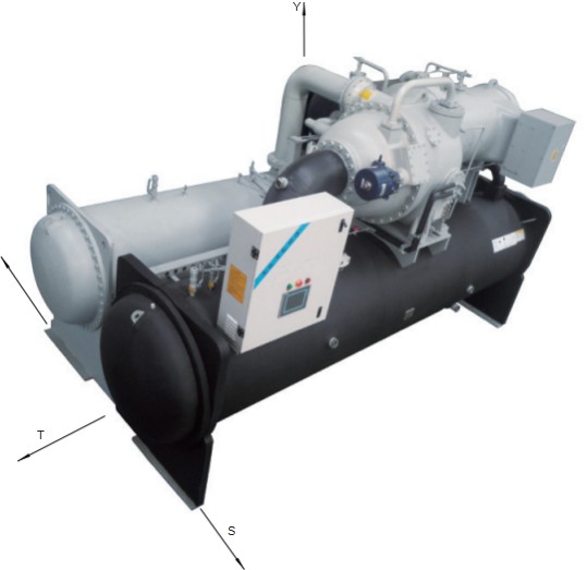
<3> Regardless of unit type, allow sufficient maintenance clearance on each side. Also leave adequate space at both ends of the unit for future cleaning and replacement or repair of the condenser and evaporator copper tubes.
<4> The indoor plant room must have adequate ventilation to ensure safe equipment operation and facilitate operation.
<5> To ensure that electrical components operate properly, do not install the unit in areas with dust, dirt, corrosive fumes, or high humidity. If such conditions exist, they must be corrected.
3. Unit Foundation
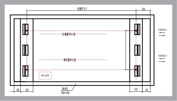
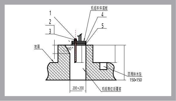
The foundation may be made of concrete or steel plate, but must be capable of fully supporting the operating weight of the unit. The levelness must be within 3/1000. To facilitate unit maintenance and inspection, the foundation should be at least 250mm above floor level.
4. Vibration Isolation
<1> The unit foundation must be solid to minimize the transmission of vibration.
<2> Install vibration isolators under the unit to prevent noise and vibration from being transmitted to the floor and to reduce vibration affecting the unit.
5. Drainage
When preparing the foundation, provide a drainage trench in the floor to drain water from pipes or equipment during maintenance.
6. Water Protection
Do not install the unit beneath pipes that may produce condensation or leak, or where water may splash onto it. Water protection is very important for the safety of electrical control equipment.
7. Condenser and Evaporator Water Piping
1. Install the water piping only after the unit has been leveled. Install an automatic air vent at the highest point of all piping. Insulate the evaporator water piping to prevent condensation. Insulate the condenser water piping where necessary, in accordance with local conditions and regulations.
2. Connect the inlet and outlet water piping to the unit’s condenser and evaporator according to the unit markings. Do not connect them incorrectly.
3. Install thermometers and pressure gauges on the condenser and evaporator inlet and outlet water piping to record unit operating conditions.
4. Install filters on the inlet side of the cooling-water and air-conditioning-water pump piping. Debris may remain in the water pipes after installation and may be difficult to remove. During unit operation, such debris may enter the pumps, condenser, and evaporator, causing internal damage or blocking the heat-transfer tubes. Therefore, clean the filters after flushing and pressure-testing the water pipes to ensure clean water. When flushing the pipes, isolate the water system from the unit to prevent debris from accumulating inside the unit.
Note: Our company accepts no responsibility for unit faults caused by water quality.
5. Install shut-off valves on the condenser and evaporator inlet and outlet water piping so that the water valves can be closed and the water inside the condenser and evaporator drained during maintenance.
6. Install flexible vibration-isolating connectors at the condenser and evaporator inlet and outlet water connections to reduce vibration transmission and prevent the piping weight from being borne by the unit.
7. Water differential pressure switches are installed on the evaporator and condenser water pipes at the unit. No additional paddle flow switch is required on the site piping.
8. Install the circulating water pumps at the condenser and evaporator inlets. If space is limited, they may also be installed on the outlet side. When selecting pumps, ensure that the pump suction side is under positive pressure.
9. Install the expansion tank at the highest point of the air-conditioning equipment to maintain air-venting functionality and accommodate expansion and contraction in the water supply and chilled-water systems.
10. Install an automatic air vent at the highest point of any raised section of the water piping. Before starting the chiller, confirm that all air has been purged from the piping to prevent damage caused by operation without water.
11. If conditions may cause the unit to freeze (ambient temperature below 0℃), drain all water from the condenser and evaporator to prevent freezing and damage or rupture of the internal copper tubes. If the unit will be shut down for an extended period or not used in winter, drain the water from the evaporator and condenser.
Warning: Our company accepts no responsibility for freeze damage caused by improper operation.
8. General Water System Requirements
<1> Water quality: Use clean water or treated water that meets project requirements. Poor chilled-water and cooling-water quality can cause scale to form inside the heat-transfer tubes, reducing heat-transfer efficiency and unit performance. It can also corrode the tubes and cause serious unit faults. Customers should treat the water in accordance with GB/T 50050, “Design code for industrial recirculating cooling water treatment.” Use softened water in closed chilled-water systems. During unit operation, take regular samples of the cooling water (or chilled water in an open system) for analysis. Water quality must meet the requirements in the table below. If it does not, water treatment is required.
<2> Water temperature: The source water temperature must be appropriate.
<3> Water quantity: The water supply must be sufficient to meet the user’s heating or cooling load requirements.
9. Space Layout
Product Electrical Installation
1. High-Voltage Centrifugal Chiller Site Wiring Diagram
Note: Due to design improvements, the unit’s appearance may be updated slightly. The actual product shall prevail.
(1) High-voltage wiring instructions
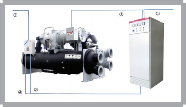
<1> Cable ① is the power cable from the customer’s high-voltage distribution cabinet to the power cabinet. The power supply must be 6KV or 10KV, 3N~50Hz. The cable enters through the top of the power cabinet. The cable size should be selected according to the unit power.
<2> Cable ② is the power cable from the power cabinet to the main motor of the centrifugal chiller. The cable exits from the top of the power cabinet. The cable size should be selected according to the unit power.
<3> Cable ③ consists of five power cables (three phases, neutral, and ground) from the customer’s site to the centrifugal chiller control cabinet. The cable size must be 2.5mm2 or larger. The power supply is 380V 3N~50Hz and must be provided separately by the customer.
<4> Cable ④ consists of 14 signal control wires from the power cabinet to the main control cabinet of the centrifugal chiller. The wire size must be 1.0mm2 or larger. Analog signal wires must be shielded.
<5> Cable ⑤ consists of signal control wires from the centrifugal chiller main control cabinet to the water pump control cabinet and for remote start/stop. The wire size must be 1.0mm2 or larger.
Note: The water pump control cabinet is supplied by the customer.
<6> Power cables and control cables must be routed separately and must not be placed in the same cable tray.
<7> All of the above wiring is to be supplied by the customer.
◎ Note: Users must provide the cables from the user’s distribution cabinet to the starter cabinet and control cabinet, the control cables for the starter cabinet, and the cables from the starter cabinet to the compressor. Install and wire the equipment according to the electrical schematic and wiring diagram supplied with the unit. The high-voltage starter cabinet provided by the user must meet our company’s technical requirements.
2. Low-Voltage Centrifugal Chiller Site Wiring Diagram
Note: Due to design improvements, the unit’s appearance may be updated slightly. The actual product shall prevail.
(1) Low-voltage wiring instructions
<1> Cable ① is the power cable (three phases, neutral, and ground) from the customer’s distribution cabinet to the power cabinet. The power supply must be 380V 3N~50Hz. The cable enters through the top of the power cabinet. The cable size should be selected according to the unit power.
<2> Cable ② is the power cable from the power cabinet to the main motor of the centrifugal chiller (star-delta or soft starting, six power cables plus ground). The cable exits from the top of the power cabinet. The cable size should be selected according to the unit power.
<3> Cable ③ consists of five power cables (three-phase) from the power cabinet to the centrifugal chiller oil pump control cabinet. The wire size must be 2.5mm2 or larger.
<4> Cable ④ consists of 14 signal control wires from the power cabinet to the main control cabinet of the centrifugal chiller. The wire size must be 1.0mm2 or larger. Analog signal wires must be shielded.
<5> Cable ⑤ consists of signal control wires from the centrifugal chiller main control cabinet to the water pump control cabinet and for remote start/stop. The wire size must be 1.0mm2 or larger.
Note: The water pump control cabinet is supplied by the customer.
<6> Power cables and control cables must be routed separately and must not be placed in the same cable tray.
◎ Note: Users must provide the cables from the user’s distribution cabinet to the starter cabinet and control cabinet, the control cables for the starter cabinet, and the cables from the starter cabinet to the compressor. Install and wire the equipment according to the electrical schematic and wiring diagram supplied with the unit. The high-voltage starter cabinet provided by the user must meet our company’s technical requirements.
Frequently Asked Questions
Please provide the model, airflow, total/static pressure, installation orientation, air inlet and outlet configuration, material, insulation, motor voltage/frequency, control method, filter module, smoke control and fire protection requirements, quantity, and packaging requirements. Performance, dimensions, and certification information are subject to the confirmed product and order documents.