


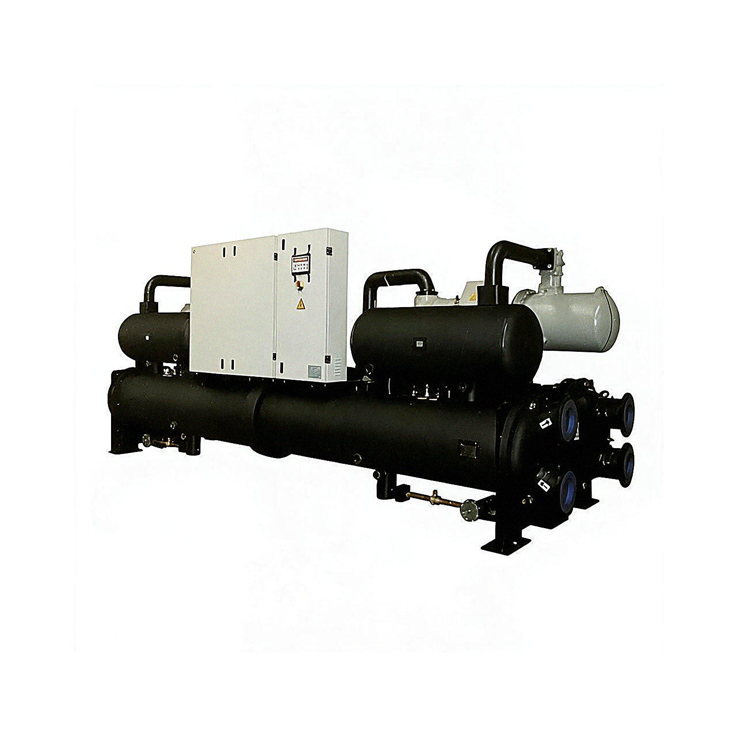
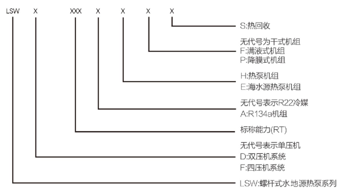
Water-Source and Ground-Source Heat Pump Unit Model Naming Rules
Design, Inspection and Manufacturing Standards
1. GB/T 19409 “Water (Ground) Source Heat Pump Units”
2. GB/T 10870 “Test Methods for the Performance of Water Chilling (Heat Pump) Packages Using the Vapor Compression Cycle”
3. NB/T 47012 “Pressure Vessels for Refrigeration Systems”
Operating Principles of Water-Source and Ground-Source Heat Pump Units
Definition of a Water-Source Heat Pump
A water-source heat pump is a system, or group of systems, that uses water as the medium to extract energy through heat pump technology for heating and cooling.
A water-source heat pump unit consumes a small amount of high-grade energy to extract low-grade heat from surface water that cannot be used directly, converting it into high-grade energy that can be used directly.
A water-source heat pump uses thermal energy in surface water for cooling and heating, and is a type of ground-source heat pump.
How a Water-Source Heat Pump Works
Shallow water sources near the Earth's surface (such as shallow groundwater, rivers, lakes and oceans) absorb solar radiation, and their temperatures are generally very stable.
In summer, the water-source heat pump unit transfers heat from the building into the water. Because the water temperature is low, it can remove heat efficiently. In winter, it extracts energy from the
water source and raises the temperature of the water on the load side through the heat pump cycle before supplying it to the building.
Typically, a water-source heat pump unit can deliver more than 4 kW of heating or cooling for every 1 kW of energy consumed.
Water-source heat pumps use water as the heat source and cooling medium in both heating and cooling modes. Water can be used as the medium for heat pump heating and cooling if it meets the following two conditions: its temperature is between 7°C and 30°C, and the water supply is sufficient. Water sources may include various types of industrial wastewater, domestic wastewater, seawater, river water and other sources, as well as various types of industrial waste heat.
Advantages of Water-Source Heat Pump Technology
Significant Environmental Benefits
A water-source heat pump uses surface water as the heat source and heat sink in an air-conditioning system that supplies chilled and hot water. For heating, it eliminates the need for boiler-room systems fired by coal, gas or oil. With no combustion, it avoids emissions and wastewater pollution. For cooling, it eliminates the cooling tower, avoiding cooling-tower noise, mold contamination and water consumption. Water-source heat pump systems are therefore environmentally friendly central air-conditioning systems that use clean, renewable energy.
The electricity used by water-source heat pumps is itself a clean energy source, but generating it consumes primary energy and produces pollutants and carbon dioxide greenhouse gas emissions. A well-designed water-source heat pump unit can reduce electricity consumption by more than 30% compared with an air-source heat pump, and by more than 70% compared with electric heating. Thus, while saving energy, water-source heat pumps also reduce pollutant emissions and the greenhouse effect associated with primary energy consumption during power generation.
Energy Efficiency
In winter, the water available to a water-source heat pump unit is typically 12–22°C, warmer than the ambient air. This raises the evaporation temperature in the heat pump cycle and improves the coefficient of performance. In summer, the water is typically 18–35°C, cooler than the ambient air. This lowers the condensing temperature during cooling, providing better cooling performance than air-cooled and cooling-tower systems and improving unit efficiency. A well-designed and installed water-source heat pump can reduce users' heating, cooling and air-conditioning operating costs by 30–40%.
Wide Range of Applications
Water-source heat pumps can be widely used for centralized heating and cooling in hotels, office buildings, schools, shopping centers, villa communities and residential communities, as well as for air conditioning in other commercial and industrial buildings. They can also be used in swimming pools, dairy processing, beer brewing, cold rolling and forging, indoor cultivation, temperature-controlled aquaculture and other industries.
Multiple Functions in One Unit
Models with heat recovery can supply chilled or hot water while using a single unit to provide both cooling and heating, as well as domestic hot water. For an air-conditioning system, one heat pump provides two heat sources, saving the initial investment. The total investment is only 60% of that of a conventional air-conditioning system. Installation is easy, requires less labor than other air-conditioning systems, takes less time and is easy to modify.
High Level of Automation
Because operating conditions are stable, water-source heat pump units can use a simple system design. They have fewer components and a high degree of automatic control.
No Pollution
The refrigerants used in water-source heat pump technology may include R22, R134a or other substitutes. Water-source heat pump units produce no pollution during operation: there is no combustion or flue gas, and no solid waste, wastewater, exhaust gas or soot. This helps create a better environment. The units can be installed in residential areas without requiring space to store fuel or waste, and without the need to transport heat over long distances.
Stable, Reliable Operation and Easy Maintenance
Water temperatures remain relatively stable throughout the year, with far less variation than air temperatures, making water an excellent heat source for heat pumps and cooling source for air conditioning. This relatively constant water temperature enables more reliable and stable heat pump operation and ensures high system efficiency and economy. It also avoids challenges associated with air-source heat pumps, such as winter defrosting. The system is simple, with fewer unit components, and operates simply and reliably. Maintenance costs are relatively low, and service life can exceed 20 years.
Definition of a Ground-Source Heat Pump
A ground-source heat pump is a type of heat pump that uses shallow geothermal energy for heating and cooling.
A heat pump is a device that transfers cooling and heat using the principles of the Carnot cycle and the reverse Carnot cycle.
A ground-source heat pump generally refers to a system that transfers heat or cooling from water in the underground soil to where it is needed. Heat pumps are typically used for air conditioning, either for cooling or
heating. Ground-source heat pumps also use the substantial heat and cooling storage capacity of the soil. In winter, they transfer heat from the ground into the building; in summer, they transfer cooling from the ground into the building, forming an annual heating and cooling cycle.
Cooling Principle
In cooling mode, the compressor in the ground-source heat pump unit drives the refrigerant through a vapor-liquid phase-change cycle. The refrigerant evaporates in the refrigerant-to-air heat exchanger, absorbing heat carried by the circulating indoor air. As the refrigerant circulates, it condenses in the refrigerant-to-water heat exchanger, where the water circuit absorbs the heat carried by the refrigerant and ultimately transfers it to groundwater or the soil. As heat is continuously transferred from indoors to the ground, the refrigerant-to-air heat exchanger cools the room.
Heating Principle
In heating mode, the compressor in the ground-source heat pump unit drives the refrigerant, and the water flow direction is reversed. The water circuit extracts heat from groundwater or the soil. The refrigerant evaporates in the refrigerant-to-water heat exchanger, absorbing heat from the water circuit. As the refrigerant circulates, it condenses in the refrigerant-to-air heat exchanger, where the air circuit absorbs the heat carried by the refrigerant. As heat is continuously transferred from the ground indoors, heating is provided through forced convection, natural convection or radiation.
Features of Ground-Source Heat Pump Units
Ground-Source Heat Pumps Use Renewable Energy
The shallow layer of the Earth's surface is a vast solar collector, capturing 47% of the solar energy radiated to the Earth, and is also a vast dynamic energy-balance system. In addition, ground-source heat pumps act as an energy storage system, storing heat in summer for use in winter. This makes the system a new technology for using renewable energy.
An Economical and Effective Energy-Saving Technology
Because the temperature of geothermal energy or shallow geothermal resources remains relatively stable, ground-source heat pumps operate 40% more efficiently than conventional air-conditioning systems and can reduce operating costs by 30–40%. They eliminate the need for a cooling tower and do not consume water.
Significant Environmental Benefits
Compared with air-source heat pumps, ground-source heat pumps can reduce pollutant emissions by more than 70%. Combining them with other energy-saving measures can further increase energy savings and emissions reductions. With no cooling tower, they do not cause contamination such as Legionnaires' disease.
Multiple Functions in One Unit and a Wide Range of Applications
Ground-source heat pump systems can provide heating, air conditioning and domestic hot water in one unit. A single system can replace the two separate systems of a boiler and an air conditioner. They can be used in hotels, shopping centers, office buildings, schools and other buildings, and are particularly suitable for heating and air conditioning in villa residences.
No Ground-Surface Area Required
Ground-source heat pump heat exchangers are buried underground and can be installed around buildings. They can be located beneath gardens, parking lots, lawns and farmland, or in lakes and ponds; they can also be installed in soil, rock or groundwater layers, or embedded in concrete foundation piles, without occupying ground-surface area. They eliminate the need for a boiler room and its associated coal and ash storage areas.
Overview of the Main Components of Water-Source and Ground-Source Heat Pump Units
When equipped with a heat recovery system, water (ground) source heat pump units can not only meet heating and cooling requirements but also supply domestic hot water, reducing equipment investment. They are energy-saving and environmentally friendly central air-conditioning systems.
Water (ground) source heat pump units feature renewable resources, high efficiency and energy savings, significant environmental and economic benefits, multiple functions in one unit and a wide range of applications. They are suitable for various small shopping centers, upscale residences, office buildings, commercial buildings, factories, department stores, hotels, hospitals and other facilities.
The unit uses a semi-hermetic twin-screw compressor and features a single- or multi-circuit design. Its components are easy to maintain.
The protection and control devices are housed in the control cabinet, and a computer display shows the main unit's operating status.
The unit is fully assembled at the factory and shipped after successful operation and commissioning tests.
This series of units is suitable for commercial and residential buildings, including shopping centers, office buildings, commercial buildings, factory workshops, hotels and hospitals.
The design, manufacture and inspection of screw-type water (ground) source heat pump units comply with GB/T 19409-2013, “Water (Ground) Source Heat Pump Units.”
Compressor
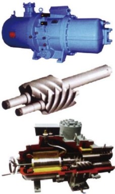
The compressor features a positive-displacement twin-screw design. The compression section consists of two intermeshing helical rotors, with the male rotor driving the female rotor. This double-torque positive-displacement design produces pure rotary motion, resulting in very low vibration and a wide operating range. The process from suction and compression to discharge is highly efficient,
with smooth airflow. The compressor is lubricated and sealed by differential-pressure oil supply, so no oil pump is required.
An efficient oil separator is built into the compressor. Integrating the oil separator and compressor into one unit minimizes the compressor's overall dimensions and simplifies the refrigerant cycle.
For non-flooded units, a secondary oil separator is installed between the discharge port and condenser to reduce the amount of refrigeration oil entering the system and improve heat exchange efficiency.
A floating capacity-control system, driven by a solenoid valve and hydraulic system, operates the slide valve for convenient part-load operation. The compressor can be adjusted in stages from 25% to 100%. Alternatively, fuzzy logic control can provide stepless capacity control, allowing output to match the building load closely.
Compared with reciprocating compressors, semi-hermetic screw compressors have the following advantages:
They have fewer moving parts (approximately one-third to one-quarter as many as reciprocating compressors), a simple structure, fewer wear parts, high reliability and a long service life.
Suction and discharge are uniform and continuous, with no pulsation. The discharge temperature is low, operating vibration is minimal, the compressor is insensitive to wet compression and has strong resistance to liquid slugging.
Shell-and-Tube Evaporator
Shell: Made from high-quality steel plate for pressure vessels. Manufacturing and testing comply with NB/T 47012-2020, “Pressure Vessels for Refrigeration Systems.” The outer surface is covered with flame-retardant, waterproof thermal insulation. The evaporator baffles are made of PVC engineering plastic, offering strong corrosion resistance and a tight seal. Chilled water flows back and forth above and below the baffles, increasing turbulence and improving the evaporator's heat transfer capacity. A flow-distribution device at the refrigerant inlet ensures even refrigerant distribution among the heat-exchange tubes and improves the overall heat transfer efficiency of the unit.
Copper tubes: High-efficiency DAC corrugated internally threaded heat-exchange tubes greatly enhance heat transfer on the refrigerant side and increase the heat transfer coefficient, ensuring effective cooling and heating.
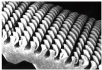

Ultra-High-Efficiency Falling-Film Evaporator
① An efficient falling-film evaporator is used. Its heat transfer efficiency is more than 15% higher than that of a conventional flooded evaporator, and it reduces unit operating costs by 30%. When used in the unit, it can achieve a coefficient of performance that meets the highest level of the national energy-efficiency certification standard. This falling-film evaporator has also been granted a national utility model patent.
② The patented invention “Real-Time Refrigerant Flow Control” provides real-time flow control in response to changes in user load. Its control accuracy is higher and unit operation is more reliable. It also provides more stable liquid-level control, allowing the unit to operate with a foundation-level deviation of up to 10%, a leading capability in the industry.
③ The independently developed, ultra-high-efficiency, low-pressure-drop oil separator has been granted a national utility model patent. Its oil separation efficiency reaches 99.99%, ensuring more reliable oil return and a longer unit service life.
④ The unit uses a domestically pioneered liquid distribution technology and a condenser refrigerant outlet structure covered by a national utility model patent. These reduce the refrigerant charge and refrigerant consumption, making the unit more environmentally friendly.
Shell-and-Tube Condenser
Shell: Made from high-quality steel plate for pressure vessels. Manufacturing and testing comply with NB/T 47012-2020, “Pressure Vessels for Refrigeration Systems.” The covers at both ends of the shell are removable for easy cleaning and maintenance.
The unit features a single- or multi-circuit refrigerant flow design. Refrigerant condenses on the shell side and releases heat, while cooling water flows through the tubes and absorbs heat.
High-efficiency DAC corrugated externally finned heat-exchange copper tubes greatly enhance heat transfer on the refrigerant side and increase the heat transfer coefficient, ensuring effective cooling and heating.
Expansion Valve
The electronic expansion valve control system provides up to 3,810 steps of control resolution. The electronic control system adjusts refrigerant flow according to suction superheat and saturation pressure, keeping the unit in optimal operating condition and enabling it to deliver maximum capacity.
Power Distribution and Control Cabinet
Includes compressor starting devices, power protectors and a microcomputer controller.
Uses wide-temperature-range electrical components from well-known brands.
The microcomputer controller operates reliably at ambient temperatures from -15°C to 65°C and provides comprehensive automatic control functions. The unit is equipped with RS-232 and
RS-485 standard communication interfaces for remote control.

Microcomputer Control Features
Chilled-water temperature setting and display.
Automatic capacity control and start/stop functions.
Touchscreen operation.
Displays current (optional) and setpoint, operating status, alarm status and compressor operating hours.
Accepts remote start and stop signals.
If a power failure occurs due to an external fault, the unit can automatically resume operation when power is restored.
Password protection is provided.
Safety Devices
High- and Low-Pressure Switches
Protect the compressor from damage caused by excessively high or low pressure.
Freeze Protection Temperature Control
Protects the system from evaporator damage caused by chilled-water freezing due to a water-system fault.
Oil Heater
Each compressor is equipped with an oil heater. When the compressor stops, the heater warms the oil to protect the system from dilution caused by refrigerant mixing with the oil before the next startup.
Sight Glass
A sight glass with a moisture indicator is installed in the liquid line. The readable indicator allows operators to observe whether the refrigerant charge is sufficient and whether the refrigerant's moisture content exceeds the limit during operation.
High-Pressure Discharge Check Valve
Prevents high-pressure refrigerant from flowing back into the compressor when the unit is stopped.
Replaceable-Core Filter Drier
Filters contaminants in the system and absorbs moisture in the refrigerant circuit. The filter drier features a large effective flow area and very low pressure drop.
Pressure Gauges
Indicate high- and low-side pressures while the unit is operating or stopped, helping operators assess the unit's operating condition.
Emergency Stop Switch
Allows the unit to be stopped manually in an emergency.
Overload Protector
Stops the motor when its load current exceeds the rated value, protecting it from burnout.
Power Protector
Protects the compressor against excessively high or low voltage, phase reversal and phase loss.
Refrigerant Injection Device
Injects liquid refrigerant to cool the compressor and prevent excessive discharge temperatures.
Water (Ground) Source Heat Pump Unit Series: Technical Data Tables
Water-Source Heat Pump Unit Technical Data Table (I)
Notes: 1) Rated operating conditions for unit cooling capacity and compressor power consumption: condenser entering/leaving water temperatures (18/-°C), evaporator entering/leaving water temperatures (-7°C).
2) Rated operating conditions for unit heating capacity and compressor power consumption: condenser entering/leaving water temperatures (-/45°C), evaporator entering/leaving water temperatures (15/-°C).
3) Rated operating conditions for partial heat recovery: condenser entering-water temperature 40°C; evaporator entering-water temperature 12°C.
4) The standard water-side pressure rating of the condenser, evaporator and heat recovery unit is 1.0 MPa; 1.6 MPa is available to order. Fouling factors: evaporator 0.018 m²·°C/kW; condenser 0.044 m²·°C/W.
5) Specifications and parameters in this table are subject to change without notice.
6) In addition to the specifications listed above, non-standard products can be supplied according to customer requirements for performance and parameters. Heat-recovery models are optional, and non-standard units can be customized.
7) Dimensions may change due to technical improvements. Dimensions are for reference only; please request an installation drawing.
Water-Source Heat Pump Unit Technical Data Table (II)
Notes: 1) Rated operating conditions for unit cooling capacity and compressor power consumption: condenser entering/leaving water temperatures (18/-°C), evaporator entering/leaving water temperatures (-/7°C).
2) Rated operating conditions for unit heating capacity and compressor power consumption: condenser entering/leaving water temperatures (-/45°C), evaporator entering/leaving water temperatures (15/-°C).
3) Rated operating conditions for partial heat recovery: condenser entering-water temperature 40°C; evaporator entering-water temperature 12°C.
4) The standard water-side pressure rating of the condenser, evaporator and heat recovery unit is 1.0 MPa; 1.6 MPa is available to order. Fouling factors: evaporator 0.018 m²·°C/kW; condenser 0.044 m²·°C/kW.
5) Specifications and parameters in this table are subject to change without notice.
6) In addition to the specifications listed above, non-standard products can be supplied according to customer requirements for performance and parameters. Heat-recovery models are optional, and non-standard units can be customized.
7) Dimensions may change due to technical improvements. Dimensions are for reference only; please request an installation drawing.
Water-Source Heat Pump Unit Technical Data Table (III)
Notes: 1) Rated operating conditions for unit cooling capacity and compressor power consumption: condenser entering/leaving water temperatures (18/-°C), evaporator entering/leaving water temperatures (-/7°C).
2) Rated operating conditions for unit heating capacity and compressor power consumption: condenser entering/leaving water temperatures (-/45°C), evaporator entering/leaving water temperatures (15/-°C).
3) Rated operating conditions for partial heat recovery: condenser entering-water temperature 40°C; evaporator entering-water temperature 12°C.
4) The standard water-side pressure rating of the condenser, evaporator and heat recovery unit is 1.0 MPa; 1.6 MPa is available to order. Fouling factors: evaporator 0.018 m²·°C/kW; condenser 0.044 m²·°C/kW.
5) Specifications and parameters in this table are subject to change without notice.
6) In addition to the specifications listed above, non-standard products can be supplied according to customer requirements for performance and parameters. Heat-recovery models are optional, and non-standard units can be customized.
7) Dimensions may change due to technical improvements. Dimensions are for reference only; please request an installation drawing.
Water-Source Heat Pump Unit Technical Data Table (IV)
Notes: 1) Rated operating conditions for unit cooling capacity and compressor power consumption: condenser entering/leaving water temperatures (18/-°C), evaporator entering/leaving water temperatures (-7°C).
2) Rated operating conditions for unit heating capacity and compressor power consumption: condenser entering/leaving water temperatures (-/45°C), evaporator entering/leaving water temperatures (15/-°C).
3) Rated operating conditions for partial heat recovery: condenser entering-water temperature 40°C; evaporator entering-water temperature 12°C.
4) The standard water-side pressure rating of the condenser, evaporator and heat recovery unit is 1.0 MPa; 1.6 MPa is available to order. Fouling factors: evaporator 0.018 m²·°C/kW; condenser 0.044 m²·°C/kW.
5) Specifications and parameters in this table are subject to change without notice.
6) In addition to the specifications listed above, non-standard products can be supplied according to customer requirements for performance and parameters. Heat-recovery models are optional, and non-standard units can be customized.
7) Dimensions may change due to technical improvements. Dimensions are for reference only; please request an installation drawing.
Water-Source Heat Pump Unit Technical Data Table (V)
Notes: 1) Rated operating conditions for unit cooling capacity and compressor power consumption: condenser entering/leaving water temperatures (18/-°C), evaporator entering/leaving water temperatures (-/7°C).
2) Rated operating conditions for unit heating capacity and compressor power consumption: condenser entering/leaving water temperatures (-/45°C), evaporator entering/leaving water temperatures (15/-°C).
3) Rated operating conditions for partial heat recovery: condenser entering-water temperature 40°C; evaporator entering-water temperature 12°C.
4) The standard water-side pressure rating of the condenser, evaporator and heat recovery unit is 1.0 MPa; 1.6 MPa is available to order. Fouling factors: evaporator 0.018 m²·°C/kW; condenser 0.044 m²·°C/kW.
5) Specifications and parameters in this table are subject to change without notice.
6) In addition to the specifications listed above, non-standard products can be supplied according to customer requirements for performance and parameters. Heat-recovery models are optional, and non-standard units can be customized.
7) Dimensions may change due to technical improvements. Dimensions are for reference only; please request an installation drawing.
Handling and Installation Precautions
1. Installation Location:
a. The location must be clean and dry, free of stored items and well lit to facilitate checking control instruments and performing operation and maintenance.
b. Avoid locations exposed to direct sunlight or direct radiation from other heat sources.
c. Locate the unit near the power supply for convenient wiring.
d. The floor must be sturdy and unlikely to cause resonance or noise.
e. Install indoors in a well-ventilated area with low humidity and little dust or sand.
f. Do not install the unit beneath sweating or leaking water pipes or where water may splash onto it. Waterproofing is essential to the safety of electrical control equipment.
2. Space Requirements:
Allow sufficient space to move the unit into and out of the equipment room, and provide adequate maintenance clearance on all sides. A clearance of 1 m on each side is recommended. Leave sufficient space at both ends of the unit for cleaning and replacing the condenser and evaporator copper tubes; a clearance of 2.6 m is recommended.
3. Foundation:
a. The foundation may be made of concrete or steel plate, but must be able to support the unit's operating weight. Levelness must be within 3/1000.
b. When installing the unit on a roof or balcony, ensure that the floor can support its operating weight.
c. Provide a floor drain to dispose of water from pipes or equipment during maintenance.
d. To prevent the transmission of vibration and noise during operation, install vibration-isolation pads between the unit base and foundation.
4. Receipt and Inspection:
a. When the unit arrives at the delivery location specified in the contract, the user should arrange for personnel to unpack and inspect it.
b. Check that all supplied accessories are present.
c. Check the unit for damage and verify that all components are present.
d. Check the unit system for leaks.
After completing the above inspections, promptly report any damage or questions to our company or local office so that they can be handled appropriately.
Note: Take protective measures when unpacking and inspecting the equipment to prevent damage.
5. Handling:
Keep the unit vertical during lifting. The tilt angle must be less than 15°. Avoid impacts and sliding. Personnel must not stand beneath or near the unit.
a. Rolling: Place several rollers of the same diameter beneath the unit base. Each roller must be slightly longer than the outer frame of the base and suitable for balancing the unit.
b. Lifting: The lifting ropes or slings must have a load capacity at least twice the unit's weight, and the hooks must be securely attached to the unit. The lifting
angle must exceed 60°. Use the lifting holes provided in the unit base. Do not use any other points for lifting.
Note: Protect the unit appropriately during lifting to avoid damage. Do not allow it to strike the ground, as excessive impact may damage the unit.
Install the water pipes only after leveling the unit. Install an automatic air vent at the highest point of the piping. Insulate the evaporator water pipes to prevent condensation. Insulation of the condenser water pipes should be provided as required by local conditions and regulations.
Connect the inlet and outlet water pipes to the condenser and evaporator of the chiller according to the unit markings. Do not reverse the connections.
Install thermometers and pressure gauges on the condenser and evaporator inlet and outlet pipes to monitor unit operation.
Install a filter on the inlet side of the chilled-water pump. Debris may remain inside the water pipes after installation and may be difficult to remove. During operation, it could enter the pump, condenser or evaporator and cause blockages or damage to the heat-transfer tubes.
Install shutoff valves on the condenser and evaporator inlet and outlet pipes so they can be closed during maintenance to drain water from the condenser and evaporator.
Install flexible vibration-isolating hoses at the condenser and evaporator water-pipe connections to reduce vibration transmission and prevent the unit from bearing the weight of the piping.
Install a flow control valve at the condenser water inlet to control water flow and maintain appropriate condensing pressure.
Install flow switches at the condenser and evaporator outlets to ensure normal water flow while the unit is operating. Failure to do so may cause serious damage to the unit.
Install the circulating water pump at the condenser and evaporator inlets. If space is limited, it may also be installed on the outlet side.
Install the expansion tank at the highest point of the air-conditioning equipment to facilitate air venting and accommodate expansion and contraction in the water supply and chilled-water systems. Install an automatic air vent at the highest point of raised sections of the water piping. Before starting the chiller, confirm that all air has been
removed from the water pipes to prevent damage caused by operation without water.
Before commissioning the unit, ensure that the water system has been thoroughly flushed. Other requirements must comply with the relevant design and construction standards. General water-system requirements:
Water quality: Clean water or treated water that meets project requirements.
Water temperature: The water source temperature must be appropriate.
Water flow: The water supply must be sufficient to meet the user's heating or cooling load.
Power Supply and Distribution
Electrical work must comply with applicable regulations.
Wire sizes, electromagnetic switches, fuse-free circuit breakers and other specifications must comply with applicable regulations.
The power supply phase sequence must match the compressor's direction of rotation.
All wiring terminals must be uniform and properly connected, and all screws must be tightened.
Label the wiring after connection to facilitate future maintenance.
Control Circuit
Ensure that the contacts in the external interlock circuit of the control circuit are properly connected to prevent the compressor from starting before the water pump and other equipment are running.
Do not disconnect power to the oil heater when the unit is stopped. If power has been disconnected, before restarting, confirm that the oil heater has been on for 8 hours or that the oil temperature is above 23°C.
Correction Factor Table for Water (Ground) Source Heat Pump Units
Correction Factors for Unit Cooling Conditions
Correction Factors for Unit Heating Conditions
Estimated Air-Conditioning Loads for Water (Ground) Source Heat Pump Units
Note: The values above are estimates. Calculating each air-conditioned room individually will provide greater accuracy.
a) The values above include the cooling (heating) load from fresh air (coefficient or infiltration).
b) The data above are for the Jinan region; apply the corresponding coefficients for other regions.
c) When selecting a cooling unit, account for the simultaneous-use factor of the building's air-conditioning system; this factor is less than 1.
Frequently Asked Questions
Please provide the model, airflow, total/static pressure, installation orientation, air inlet and outlet configuration, material, insulation, motor voltage/frequency, control method, filter module, smoke control and fire protection requirements, quantity, and packaging requirements. Performance, dimensions, and certification information are subject to the confirmed product and order documents.