


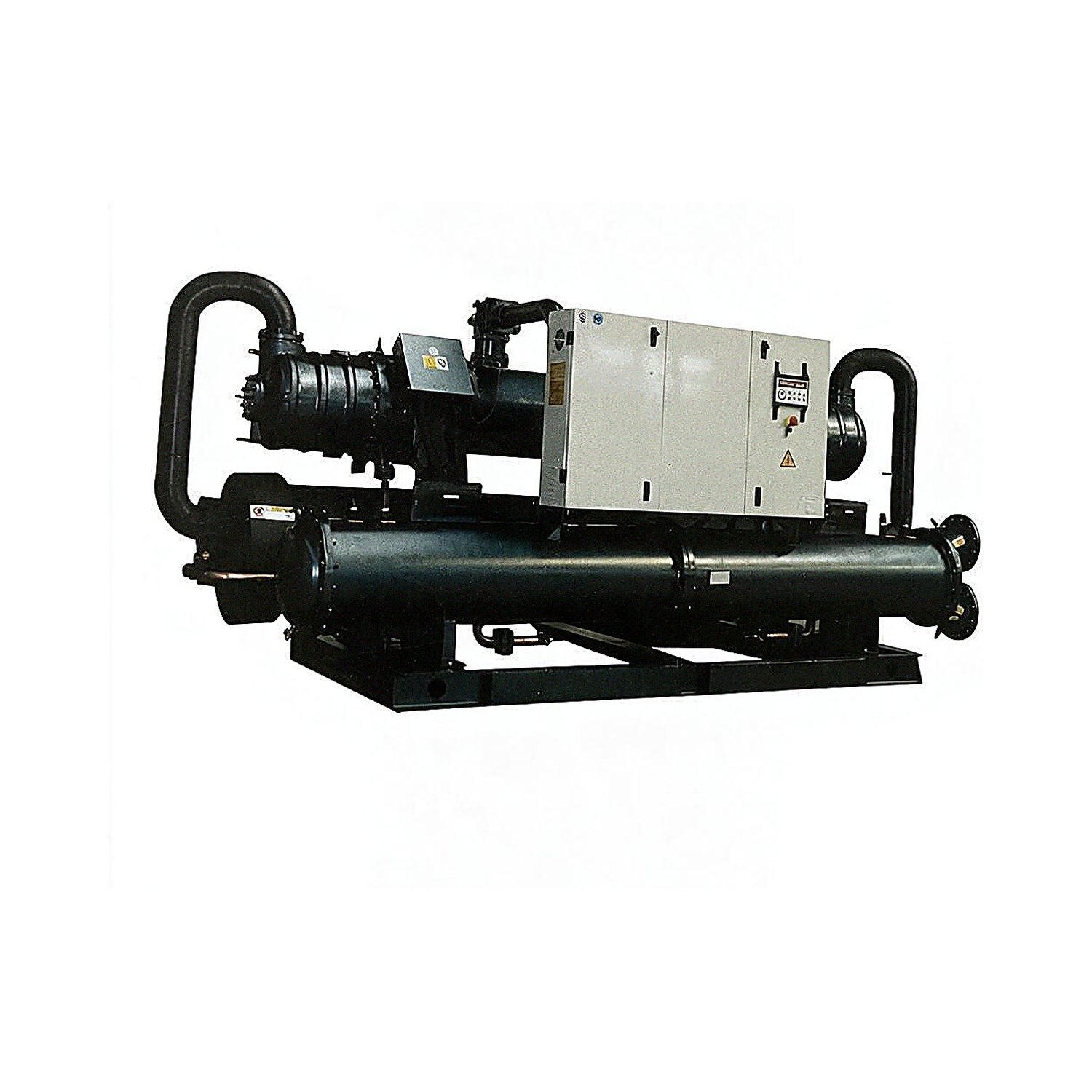
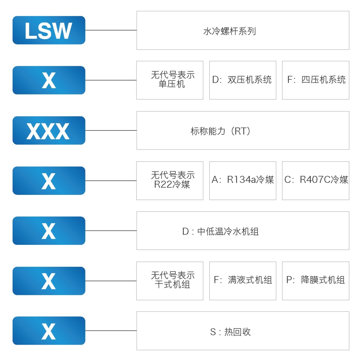
Water-Cooled Screw Chiller Model Nomenclature
Design, Inspection and Manufacturing Standards
1. GB/T 18430.1, “Water-Chilling (Heat Pump) Packages Using the Vapor Compression Cycle—Part 1: Water-Chilling (Heat Pump) Packages for Industrial or Commercial and Similar Applications”
2. GB/T10870, “Methods of Performance Testing for Water-Chilling (Heat Pump) Packages Using the Vapor Compression Cycle”
3. NB/T 47012, “Pressure Vessels for Refrigeration Systems”
4. JB/T 7659.3, “Auxiliary Equipment for Halocarbon Refrigeration Systems—Part 3: Dry-Type Evaporators”
Product Applications
Water-cooled screw chillers are widely used in comfort air-conditioning systems for public facilities such as hotels, shopping malls, office buildings, exhibition centers, airports and sports stadiums. They also meet the varying requirements of process air-conditioning systems in industries such as electronics, pharmaceuticals, biotechnology, textiles, chemicals, metallurgy, power generation and mechanical engineering.
Water-Cooled Screw Chiller Overview
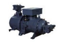
The water-cooled screw chiller uses a semi-hermetic twin-screw compressor. The unit is designed with a single or multiple refrigerant circuits, and its components are easy to maintain.
The protection and control devices are housed in the control cabinet, and the computer display shows the operating status of the main unit. The unit is fully assembled at the factory and shipped only after it has passed operation and commissioning tests. This series of units is suitable for shopping malls, office buildings, commercial buildings, factory workshops, hotels, hospitals and other commercial and residential buildings.
The design, manufacture and inspection of water-cooled screw chillers comply with GB/T18430.1-2007, “Water-Chilling (Heat Pump) Packages Using the Vapor Compression Cycle—Part 1: Water-Chilling (Heat Pump) Packages for Industrial or Commercial and Similar Applications.”
1. Equipped with a High-Quality, High-Efficiency Compressor from a Leading Brand
The unit uses a semi-hermetic screw compressor from a well-known brand. Compared with a reciprocating compressor, the semi-hermetic screw compressor offers the following advantages:
① Fewer parts (approximately one-third the number in a reciprocating compressor), a simple structure, fewer wearing parts, high reliability and long service life;
② Smooth, continuous suction and discharge, low discharge temperature, low vibration, low sensitivity to wet compression and strong resistance to liquid slugging;
③ COP of up to 4.6 or higher for dry-type units, and up to 5.3 or higher for flooded/falling-film units;
④ Superior capacity control, with stepless capacity modulation from 25% to 100%.
2. Shell-and-Tube Evaporator
1. Dry-Type Shell-and-Tube Evaporator with High-Efficiency Heat-Transfer Tubes
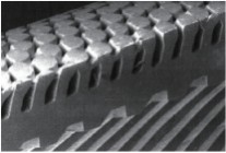
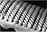
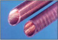
① Uses advanced DAE high-efficiency evaporator tubes. Multiple helical micro-fins and helical protrusions on the inner tube surfaces significantly improve the heat-transfer coefficient and capacity.
② The evaporator’s internal structure is optimized and fitted with a high-efficiency liquid distributor to ensure even refrigerant distribution throughout the system.
③ The sealing structure of the chilled-water baffles is improved to prevent leakage, greatly enhancing the evaporator’s heat-transfer efficiency and ensuring high unit performance.
④ A unique heat-exchanger refrigerant-flow design ensures proper system matching and balances the refrigerant flow with the water-side cooling capacity, making full use of the heat exchanger’s efficiency. Proper system matching also reduces energy consumption.
2. Ultra-High-Efficiency Falling-Film Evaporator
(1) Designed with a single- or dual-circuit refrigerant system: refrigerant absorbs heat and evaporates on the shell side while chilled water flows through the tubes and is cooled. All heat-transfer tubes are wetted with refrigerant, effectively improving heat-transfer efficiency and increasing the evaporation temperature.
(2) Shell: Manufactured and tested in accordance with NB/T47012-2020, “Pressure Vessels for Refrigeration Systems.”
(3) Copper tubes: Uses seamless copper tubes specially designed for flooded units, featuring advanced internal and external enhanced-fin technology.
(4) Works effectively with the electronic expansion valve to control the liquid level, enabling the unit to operate at its optimum condition.
(5) Compared with a flooded evaporator, a falling-film evaporator reduces the refrigerant charge, improves heat-transfer efficiency by approximately 10%, provides more stable oil return and ensures more reliable operation.
3. Shell-and-Tube Water-Cooled Condenser with High-Efficiency Heat-Transfer Tubes
① Uses advanced DAE high-efficiency condenser tubes. Multiple helical micro-fins and helical protrusions on the outer tube surfaces significantly improve the heat-transfer coefficient and capacity.
② The internal structure is optimized to greatly improve the condenser’s resistance to corrosion and fouling and maximize heat-transfer performance, ensuring high unit performance.
③ The shell-and-tube condenser is also fitted with safety and vent valves to ensure safe operation and facilitate cleaning and maintenance.
4. Vibration-Isolation Design for Low Noise and Vibration
① Spring or rubber vibration isolators are installed beneath the compressor. With vibration isolation efficiency of over 85%—a vibration transmissibility of less than 0.15—they reduce vibration in both the unit and the system, thereby lowering noise.
② All pipes in the unit system are secured with vibration-isolating plastic clamps to reduce noise caused by unit and system vibration.
5. Refrigeration Components from Leading Brands
① All refrigeration components are sourced from leading manufacturers. Removable filter-driers, expansion valves, solenoid valves, sight glasses, high- and low-pressure sensors, and other components are supplied by world-class brands to ensure high unit performance.
② All materials are inspected and approved before entering the factory to ensure high reliability of the unit’s refrigeration system.
6. Advanced, Highly Reliable Intelligent Control System and Control Technology
① In addition to the automation configuration and functions of individual units, the multi-unit control system displays the operating status of multiple units and uses return-water temperature to automatically determine whether some or all units in the air-conditioning system should operate.
② Equipped with RS485/RS232 communication interfaces for convenient centralized and remote monitoring of the units.
③ The unit balances the operation of multiple compressors to ensure efficient operation.
④ Falling-film units use the nationally patented invention “Real-Time Refrigerant Flow Control” for more precise and stable operation.
7. Unit Capacity Control
The unit uses logic calculations based on the chilled-water return or supply temperature to control its operating status and start/stop sequence. Each unit uses staged or stepless capacity control for efficient, energy-saving operation.
8. Rational Unit Design for Convenient Installation, Commissioning and Maintenance
① The unit layout is designed according to ergonomic principles, with optimized installation and service clearances to facilitate routine cleaning, servicing and repairs.
② The unit is shipped fully assembled. The low-pressure section is insulated before shipment, and the system is charged with refrigerant and oil. After delivery to the site, only the water piping needs to be connected. The unit can be started once the power supply is connected.
③ The computer automatically starts the water-pump motor and compressor according to the programmed sequence and coordinates refrigeration, time delays, interlocks, protection and automatic temperature control. The unit then operates at the set temperature under computer control and automatically adjusts its capacity in response to changes in the evaporator inlet-water temperature.
The unit is easy to install and can be controlled either locally or remotely, making inspection and maintenance straightforward.
9. The high efficiency and stability of falling-film chillers enable them to fully replace flooded chillers. Falling-film chillers offer the following advantages:
① The high-efficiency falling-film evaporator provides heat-transfer efficiency more than 15% higher than that of a conventional flooded evaporator, while reducing unit operating costs by 30%. Its use enables a unit coefficient of performance to reach the national Grade 1 energy-efficiency certification standard. The falling-film evaporator has also been granted a national utility model patent.
③ Uses the nationally patented invention “Real-Time Refrigerant Flow Control” to adjust flow in real time according to changes in the user’s load. This provides more precise control and more reliable unit operation. The unit’s liquid-level control is also more stable, and the tolerance requirement for the levelness of the installation foundation is within 10%, a leading level in the industry.
③ Uses an ultra-high-efficiency, low-pressure-drop oil separator independently developed and granted a national utility model patent. Its oil-separation efficiency reaches 99.99%, ensuring more reliable oil return and a longer service life for the unit.
⑤ Uses industry-leading liquid distribution technology and a refrigerant outlet structure for the condenser covered by a national utility model patent. These reduce the refrigerant charge and consumption, making the unit more environmentally friendly.
⑥ Intelligent remote monitoring technology provides functions including SMS alerts for unit alarms, remote troubleshooting and storage of unit operating data. This gives users greater confidence and improves operating efficiency.
Water-Cooled Screw Chiller Technical Specifications
Water-Cooled Screw Chiller Technical Specifications Table (1)
Notes: 1) Rated conditions for unit cooling capacity and compressor power consumption: condenser inlet/outlet water temperatures (30/35℃), evaporator inlet/outlet water temperatures (12/7℃).
2) Rated conditions for partial heat recovery: condenser inlet-water temperature 40℃; evaporator inlet-water temperature 12℃.
3) Standard water-side pressure rating of the condenser, evaporator and heat-recovery unit: 1.0MPa. Fouling factors: evaporator 0.018㎡℃/kW; condenser 0.044㎡℃/kW.
4) Specifications and parameters listed in this table are subject to change without notice.
Water-Cooled Screw Chiller Technical Specifications Table (2)
Notes: 1) Rated conditions for unit cooling capacity and compressor power consumption: condenser inlet/outlet water temperatures (30/35℃), evaporator inlet/outlet water temperatures (12/7℃).
2) Rated conditions for partial heat recovery: condenser inlet-water temperature 40℃; evaporator inlet-water temperature 12℃.
3) Standard water-side pressure rating of the condenser, evaporator and heat-recovery unit: 1.0MPa. Fouling factors: evaporator 0.018㎡℃/kW; condenser 0.044㎡℃/kW.
4) Specifications and parameters listed in this table are subject to change without notice.
Water-Cooled Screw Chiller Technical Specifications Table (3)
Notes: 1) Rated conditions for unit cooling capacity and compressor power consumption: condenser inlet/outlet water temperatures (30/35℃), evaporator inlet/outlet water temperatures (12/7℃).
2) Rated conditions for partial heat recovery: condenser inlet-water temperature 40℃; evaporator inlet-water temperature 12℃.
3) Standard water-side pressure rating of the condenser, evaporator and heat-recovery unit: 1.0MPa. Fouling factors: evaporator 0.018㎡℃/kW; condenser 0.044㎡℃/kW.
4) Specifications and parameters listed in this table are subject to change without notice.
Water-Cooled Screw Chiller Technical Specifications Table (4)
Notes: 1) Rated conditions for unit cooling capacity and compressor power consumption: condenser inlet/outlet water temperatures (30/35℃), evaporator inlet/outlet water temperatures (12/7℃).
2) Rated conditions for partial heat recovery: condenser inlet-water temperature 40℃; evaporator inlet-water temperature 12℃.
3) Standard water-side pressure rating of the condenser, evaporator and heat-recovery unit: 1.0MPa. Fouling factors: evaporator 0.018㎡℃/kW; condenser 0.044㎡℃/kW.
4) Specifications and parameters listed in this table are subject to change without notice.
Water-Cooled Screw Chiller Technical Specifications Table (5)
Notes: 1) Rated conditions for unit cooling capacity and compressor power consumption: condenser inlet/outlet water temperatures (30/35℃), evaporator inlet/outlet water temperatures (12/7℃).
2) Rated conditions for partial heat recovery: condenser inlet-water temperature 40℃; evaporator inlet-water temperature 12℃.
3) Standard water-side pressure rating of the condenser, evaporator and heat-recovery unit: 1.0MPa. Fouling factors: evaporator 0.018㎡℃/kW; condenser 0.044㎡℃/kW.
4) Specifications and parameters listed in this table are subject to change without notice.
Water-Cooled Screw Chiller Technical Specifications Table (5)
Notes: 1) Rated conditions for unit cooling capacity and compressor power consumption: condenser inlet/outlet water temperatures (30/35℃), evaporator inlet/outlet water temperatures (12/7℃).
2) Rated conditions for partial heat recovery: condenser inlet-water temperature 40℃; evaporator inlet-water temperature 12℃.
3) Standard water-side pressure rating of the condenser, evaporator and heat-recovery unit: 1.0MPa. Fouling factors: evaporator 0.018㎡℃/kW; condenser 0.044㎡℃/kW.
4) Specifications and parameters listed in this table are subject to change without notice.
Handling and Installation Precautions
1. Installation Location:
a. The location must be clean and dry, free of stored items, and well lit to facilitate inspection of control instruments, operation and maintenance.
b. Avoid locations exposed to direct sunlight or direct radiation from other heat sources.
c. Locate the unit close to the power supply for convenient wiring.
d. The floor must be sturdy and unlikely to cause resonance or noise.
e. Install indoors in a well-ventilated area with low humidity and little dust.
f. Do not install the unit beneath sweating or leaking water pipes, or where it may be splashed with water. Keeping water away is essential for the safety of electrical control equipment.
2. Space Requirements:
Allow sufficient space to move the unit into and out of the machine room. Provide adequate maintenance clearance on each side; 1m on each side is recommended. Allow sufficient space at both ends for cleaning and replacing condenser and evaporator copper tubes; 2.6m of clearance is recommended.
3. Foundation:
a. The foundation may be made of concrete or steel plate, but it must adequately support the operating weight of the unit. Levelness must be within 3/1000.
b. When installing the unit on a roof or balcony, pay particular attention to whether the floor can support its operating weight.
c. Provide a floor drain to discharge water from piping or equipment during maintenance.
d. To prevent the transmission of vibration and noise during operation, install vibration-isolation pads between the unit base and the foundation.
4. Receipt and Inspection:
a. When the unit arrives at the delivery location specified in the contract, the user should arrange for personnel to unpack and inspect it.
b. Check that all accessories supplied with the unit are present.
c. Check the unit for damage and verify that all parts are present.
d. Check the unit system for leaks.
After completing the inspection, promptly notify our company or local office of any damage or questions so that they can be properly addressed.
Note: Take protective measures when unpacking and inspecting the equipment to avoid damage.
5. Handling:
Keep the unit upright when hoisting. The tilt angle must be less than 15°. Avoid impacts and slipping. Personnel must not stand beneath or near the unit.
a. Rolling: Place several rollers of the same diameter beneath the unit base. Each roller must be slightly longer than the outer frame of the base and suitable for keeping the unit balanced.
b. Hoisting: The rated capacity of the lifting wire ropes or slings must be at least twice the unit weight. Ensure that the hooks are securely attached to the unit, and that the lifting angle is greater than 60°. Use the lifting holes provided in the unit base; no other points may be used for lifting.
Note: Protect the unit appropriately during hoisting to avoid damage. Do not allow it to strike the ground or suffer a strong impact, which could damage the unit.
Condenser and Evaporator Piping
1. Install the water piping only after the unit has been leveled. Install an automatic air vent at the highest point of all piping. Insulate the evaporator water piping to prevent condensation. Insulate the condenser water piping where necessary, as required by local conditions and regulations.
2. Connect the inlet and outlet water pipes to the unit condenser and evaporator according to the unit markings. Do not reverse the connections.
3. To record unit operating conditions, install thermometers and pressure gauges on the condenser and evaporator inlet and outlet water pipes.
4. Install filters on the inlet sides of the cooling-water and air-conditioning-water pumps. Debris may remain inside the pipes after installation and may be difficult to remove. During operation, it could enter the pumps, condenser or evaporator, causing internal damage or blocking the heat-transfer tubes. Therefore, clean the filters after flushing and pressure-testing the water piping to ensure clean water. During flushing, isolate the water system from the unit to prevent debris from accumulating inside the unit.
Note: Our company accepts no responsibility for unit failures caused by water-quality problems.
5. Install shutoff valves on the condenser and evaporator inlet and outlet water pipes so that the valves can be closed during maintenance to drain water from the condenser and evaporator.
6. Install flexible anti-vibration connections at the condenser and evaporator water-pipe connections to reduce vibration transmission and prevent the unit from supporting the weight of the piping.
7. Install flow switches at the outlets of the condenser and evaporator to ensure adequate water flow during operation. Failure to do so may cause serious damage to the unit.
Warning: Our company accepts no responsibility for unit problems caused by improper installation of the flow switch. Inspect the flow switch once a year.
8. Install the circulating water pump at the inlet of the condenser and evaporator. If space is limited, it may also be installed on the outlet side. When selecting a pump, ensure that the pump suction side is under positive pressure.
9. Install the expansion tank at the highest point of the air-conditioning system to maintain air-venting capability and accommodate expansion and contraction in the water and chilled-water systems.
10. Install an automatic air vent at the highest point of any raised section of the water piping. Before starting the chiller, confirm that all air has been removed from the piping to prevent damage caused by running without water.
1 1. Whenever there is a risk of the unit freezing (ambient temperature below 0℃), completely drain the water from the condenser and evaporator to prevent freezing and damage or rupture of the internal copper tubes. Drain any remaining water from the unit evaporator and condenser during extended shutdowns or when the unit is not used in winter.
Warning: Our company accepts no responsibility for freeze damage caused by improper operation.
Water Quality
Use clean water or treated water that meets project requirements. Poor chilled-water and cooling-water quality can cause scale to form inside the heat-transfer tubes, affecting heat-exchange efficiency and reducing unit performance. It can also corrode the tubes and lead to serious unit failures. Customers should treat the water in accordance with GB/T50050, “Design Code for Industrial Recirculating Cooling Water Treatment.” Soft water must be used in closed-loop air-conditioning water systems. During unit operation, regularly take samples of cooling water (or air-conditioning water in open systems) for analysis. Water quality must meet the requirements in the table below. If it does not, water treatment is required.

Appendix
Relationship Between Copper Conductor Cross-Sectional Area and Safe Current
Example: For an operating current of 32A, select a conductor with a minimum cross-sectional area of 6mm2 and a maximum of 10mm2.
For an operating current of 160A, select a conductor with a minimum cross-sectional area of 50mm2 and a maximum of 95mm2; 70mm2 is also available as an intermediate option.
Note: The conductor cross-sectional areas above are based on copper conductors that comply with national standards.
Note: The values above are estimates. Calculating each air-conditioned room individually will provide greater accuracy.
a) The values above include cooling (heating) loads from outdoor air, whether due to ventilation rates or infiltration.
b) When selecting a chiller, consider the simultaneous-use factor for the building’s air-conditioning system; this factor is
Frequently Asked Questions
Please provide the model, airflow, total/static pressure, installation orientation, air inlet and outlet configuration, material, insulation, motor voltage/frequency, control method, filter module, smoke control and fire protection requirements, quantity, and packaging requirements. Performance, dimensions, and certification information are subject to the confirmed product and order documents.