


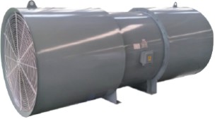
Overview of SDS Series Jet Fans
The SDS series jet fans are new products developed by our company. Our Technical Research Center has been committed to the ongoing research and development of theoretical technologies and technological innovation. We also maintain extensive exchanges and cooperation with well-known domestic companies and institutions, including Shengu Group and Xi’an Jiaotong University, and consult experts from metro design institutes, tunnel design institutes, and tunnel installation companies. Through this work, we have gained a thorough understanding of the fan’s operating requirements and accumulated extensive experience in product technology, quality requirements, and operating conditions.
This series of fans features low noise, high airflow, and high thrust. All performance indicators meet the requirements of JB/T10489-2004, Technical Conditions for Jet Fans for Tunnels. The fans are widely used for ventilation in metro, highway, and railway tunnels. They are generally suspended from the tunnel ceiling or mounted on its sides, taking up no traffic space and requiring no additional air ducts.
The SDS series jet fans are available in sizes from Φ630mm to Φ1600mm and are divided into two main types: unidirectional axial fans and reversible (bidirectional) axial fans. Maximum thrust is 3500N. High-efficiency, low-noise fans can be selected for any load and operating condition.
The SDS series jet fans are manufactured using advanced processes to ensure high quality. The fan casing is rolled and flanged using advanced, specialized equipment from China and abroad. The inner wall at the front of the impeller is machined to ensure the casing’s concentricity and strength, as well as the radial clearance of the blades. The exterior undergoes high-quality pretreatment, including dip degreasing, iron phosphating, and passivation, followed by electrostatic spraying and baking. The finish is attractive, with excellent paint adhesion, strength, and corrosion resistance, reaching a leading level in the industry. The fan blades and hubs are produced using advanced fully CNC-controlled boring and milling centers and die-casting molds, with aluminum alloy formed by high- or low-pressure die casting. The fan’s performance indicators, corrosion resistance, reliability, economy, and other technical, quality, and economic requirements are fully suited to use in all types of tunnels and metro systems.
Selection Parameters for SDS Series Jet Fans
1. Operating Conditions
In infrastructure projects such as metro, highway, and railway tunnels, forced ventilation is used to meet air-quality and safety requirements. A ventilation system must maintain good air quality over the long term; otherwise, it can be harmful to people, as illustrated in the figure.
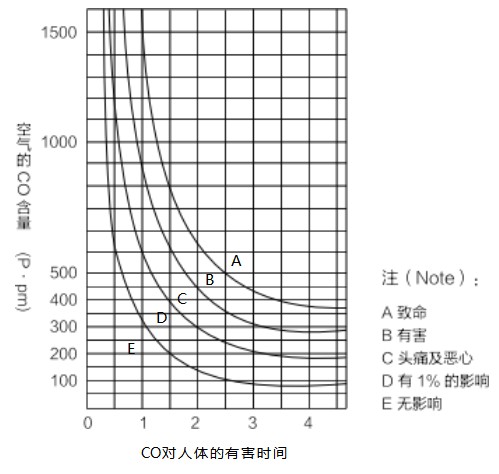
Effects of carbon monoxide on human health:
As vehicles continuously pass through a tunnel, toxic gases accumulate. If the natural air inside the tunnel is not exchanged sufficiently and in a timely manner, this inevitably poses a health hazard (see the curve showing the time-dependent effects on the human body). Forced ventilation is therefore required to supply sufficient fresh air to the tunnel while removing harmful gases.
In short, these fans are used in metro, highway, and railway tunnels mainly to reduce CO concentrations to permitted levels and prevent pollution from gasoline and diesel engine exhaust, such as NO, NO2, and NO3. In emergencies, smoke emissions must be controlled as required. The WHO-recommended value for NO2 is now widely used internationally in place of the former CO value as a key ventilation control parameter. Visibility for moving vehicles and escape routes for tunnel occupants must also be maintained. Tunnel ventilation systems must therefore ensure the safety of vehicles and people in the event of an incident. The safety and reliability, reversible operation, and high-temperature resistance of SDS series fans have all been designed with these requirements in mind. In particular, the high-temperature resistance of our fans has been tested by the National Fire Protection Testing Center. Before shipment, our products undergo safety performance testing to ensure product quality.
2. Basis for Tunnel Ventilation System Design and Product Selection
1. Traffic tunnels can generally be divided into three categories: metro, highway, and railway tunnels.
2. The prerequisite for safe and reliable operation under both normal and emergency conditions is an environmental control system that ensures coordination among all systems so they can function effectively.
A. Mechanical systems: ventilation, fire protection, and wastewater discharge
B. Power systems: power supply, power transmission and distribution, and emergency power
C. Lighting systems: general lighting, local lighting, and illuminated signs D. Communication systems: telephones, radio, and computer terminals E. Traffic systems: lights, signals, signs, and monitoring F. Control systems: monitoring traffic conditions and equipment operation
3. Tunnel ventilation systems can use any of the following three basic configurations or a combination of them.
A. Longitudinal ventilation system: This is the most basic ventilation method. Fresh air flows from the tunnel entrance to the exit, and no ventilation ducts are required along the tunnel. This system generally uses reversible jet fans installed on the ceiling or sides of the tunnel to provide ventilation in both directions and control smoke. For longer tunnels, an additional central supply and exhaust shaft connected to the atmosphere is required, forming a mixed ventilation system.
B. Full transverse ventilation system: Supply and exhaust ducts run along the tunnel. Fresh air is collected centrally through an air intake tower, while exhaust air is discharged through an exhaust tower. The supply duct is generally located below the road surface, and the exhaust duct above the traffic lanes. Supply and exhaust openings are provided at regular intervals along both ducts to remove smoke across the tunnel cross-section during an incident.
C. Semi-transverse ventilation system: This system can be divided into supply-air and exhaust-air configurations. The exhaust-air configuration is generally used. Fresh air enters through the tunnel portals, while exhaust air is handled in a manner similar to that of a full transverse ventilation system.
4. Factors to consider in tunnel ventilation system design:
A. Project investment B. Electrical capacity C. Operating costs
D. Air quality E. Safety factors F. Safeguards for emergency conditions
5. Factors affecting the number and size of fans selected for a tunnel ventilation system:
A. CO, NOOx, and smoke concentrations B. Traffic volume (traffic density and speed)
C. Wind load (tunnel length × width × height) D. Exhaust emissions (vehicle age and number) E. Emergency measures in the event of fire
6. Theoretical Basis for Calculating Tunnel Ventilation System Thrust
Tunnel ventilation system thrust is calculated based on:
Pressure losses at the inlet and outlet
Friction coefficients of tunnel surfaces and equipment
Vehicle friction coefficient (calculated under the most adverse conditions, accounting for vehicle motion or the piston effect)
Effects of external wind speed on the tunnel entrance and exit under the most adverse conditions, as well as tunnel terrain and location (gradient and elevation)
Thrust required in the event of fire (temperature, pressure, and time)
The theoretical conversion of tunnel pressure drop (Pa) into the thrust (N) required from jet fans
The thrust of a jet fan is the change in momentum between the airflow at the fan inlet and outlet, i.e. the fan thrust.
Ns-C1 × mass flow rate × airflow velocity (N), where Ns = fan static thrust (ISO), in N
C1 = empirical correction factor; mass flow rate = air density × volume flow rate
The relative velocity between jet fans used in a tunnel and the airflow inside the tunnel, the tunnel friction coefficient, and the effects of parallel fans installed in the same group are interrelated. Therefore, the effective thrust of a jet
fan is:
Ne=Nsx(1-Vt/Vj)C2xC3
where Ne = effective fan thrust (N); Vt = air velocity in the tunnel (m/s);
Vj = jet velocity (m/s); C2 = tunnel friction coefficient;
C3 = flow-direction loss due to parallel fans in the same group (this loss may be disregarded if the fans are spaced at least 100 fan diameters apart, so that their jet velocities do not affect the airflow direction).
7. Structural Features of Tunnel Jet Fans:
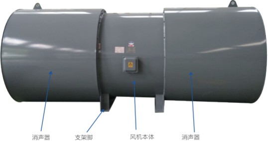
Tunnel ventilation fans are available in two configurations: unidirectional jet fans (SDS) and bidirectional jet fans [SDS(R)]. They are also available with or without silencers; the latter configuration has flow collectors (diffusers) at the inlet and outlet.
The fan casing, silencer, and support feet are formed using CNC-controlled automatic steel plate welding and machining. The exterior undergoes pretreatment, including dip degreasing, phosphating, and passivation, followed by application of water-based paint and baking to ensure fan strength, paint adhesion and hardness, and corrosion resistance.
Fan impeller: To meet tunnel ventilation requirements, the number of blades and blade angle of SDS series fans can be adjusted.
Silencer: The silencer is typically one fan diameter long. For more stringent noise requirements, it can be two fan diameters long. The silencer is bolted to the fan body.
Motor: SDS series jet fans are equipped with totally enclosed squirrel-cage motors. The motors have flange mounting plates, insulation class H, and protection rating IP55. The motor lead cable can be connected to the junction box on the fan casing. The motor is fitted with a grease nipple, which is connected by an external hose to the grease nipple on the fan casing.
Fan reversing time: In an emergency, the time required to switch the jet fan between forward and reverse operation is critical. SDS(R) fans offer electronic and mechanical reversing options and can reach rated speed in either direction within 30 seconds.
8. Testing and Inspection of SDS Series Jet Fans:
High-temperature fire testing: Successfully tested by the National Quality Supervision and Inspection Center for Fixed Fire Extinguishing Systems and Fire-Resistant Components.
Noise testing: Tests are conducted in an open area, with and without silencers fitted at the fan inlet and outlet, when the ambient wind speed is close to 0. The fan sound pressure level is measured at a 45° angle to the fan axis, 10m from the fan casing.
Thrust testing: Measured using a thrust test rig.
Fan efficiency: Defined by the measured thrust (N) and motor input power (KW) during fan operation.
These tests are conducted by our Engineering and Technical Center in strict accordance with applicable national and industry standards. The products have also passed inspection by authoritative provincial- and national-level testing organizations.
Overall Dimensions of SDS Series Jet Fans
Tunnel Jet Fan Outline Drawing
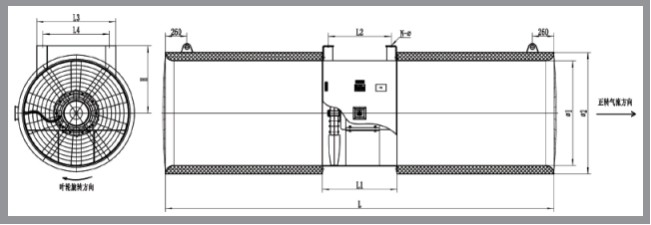
Jet Fan Dimensions
Performance Data Table for SDS Series Unidirectional Jet Fans
Performance Data Table for SDS(R) Series Bidirectional Jet Fans
Commissioning and Operation of SDS Series Jet Fans
1. After installation and before starting the fan, carefully check the following:
Check that the voltage is within the normal range (typically 380V±6%), that the three-phase lines are balanced, and that no phase is missing;
Check the fan for debris or foreign objects and remove them immediately if found;
Check that the impeller clearance meets requirements, and turn the impeller by hand to check for rubbing;
Jog the fan using the switch and check that the impeller rotates in the direction shown on the nameplate. If it does not, disconnect the power and interchange two of the power supply phase wires;
Check the grounding wire and current protection device (fuse) as required;
Only begin commissioning after completing all the checks above. If severe vibration occurs during commissioning, immediately disconnect the fan power supply and inspect the fan after it has come to a complete stop. If everything is normal, stop the fan after it has run for 10-30 minutes and check whether the impeller bolts are loose. If they are not loose, the fan is ready for standby and normal operation.
2. During normal operation, first monitor the motor current, which indicates the fan load and can signal a fault. Also check the fan and motor vibration regularly and listen for abnormal rubbing or impact noises.
3. During normal operation, stop the fan immediately for inspection or repair if any of the following occurs:
A sudden increase in current beyond the normal range;
Abnormal vibration or unusual noise;
Fan Maintenance
Before carrying out any maintenance or servicing on the fan, disconnect its power supply and hang a clearly visible warning sign at the switch to ensure safety. At least two people must be present at the work site.
Check the fan for damage every six months and repair any damage to the fan or motor coating.
Lubricate the bearings after 20,000 operating hours or two years.
Keep the fan clean. Dust buildup can increase vibration, impair motor cooling, and reduce silencer performance. Clean and maintain the fan every six months or once a year.
Frequently Asked Questions
Please provide the model, airflow, total/static pressure, installation orientation, air inlet and outlet configuration, material, insulation, motor voltage/frequency, control method, filter module, smoke control and fire protection requirements, quantity, and packaging requirements. Performance, dimensions, and certification information are subject to the confirmed product and order documents.